Turning The Crank · Volume 7
Turning the Crank — Vol 07: Reference & Cheatsheet
The six volumes before this one built an argument: one slow rotation of a handle is split by a single shaft into wind and music (Vol 01), through a drivetrain of named parts (Vol 02), whose speed sets the tempo (Vol 03) and whose lumpy load sets the effort (Vol 04), and which an electric motor can drive (Vol 05) under variable-speed control across a spectrum of automation (Vol 06). This final volume carries none of that argument forward. It is the dive’s reference apparatus — the equations, the tables, the glossary, the cross-index, and the bibliography a builder wants on the bench, gathered in one place and recomputed for internal consistency. Everything here appears earlier in prose; here it is stripped to the numbers and the citations.
Two conventions from the whole dive hold in this volume without further comment. First,
melright.com/busker is a contributor anthology, so every claim is cited by article
and author (e.g. “jsart110, Ronald Walters”), never by the site alone. Second,
crank RPM, millimetres-of-paper-per-revolution, beat spacing, flywheel inertia, and
the inputs to the worked tempo and motor examples are estimates, marked (est.),
because no hobby source states them; the relationships that bind those inputs
(v = π·d·n, the gear law, τ = F·r) are exact and are recomputed below. Imperial
figures from the source articles keep their original value with a metric equivalent
added.
7.1 Drivetrain math reference
The whole drive reduces to four relationships. Each is stated exactly, with the symbol table it uses, and each is checked against a documented hobby case in the sections that follow.
7.1.1 The four relations
Tempo (linear-speed form): v = π · d · n
Tempo (musical form): BPM = v ÷ s = (π · d · n) ÷ s = (π · d · R · n_crank) ÷ s
Speed through a gear or pulley pair: ω_out = ω_in × (T_driver ÷ T_driven)
Torque through a gear or pulley pair: τ_out = τ_in × (T_driven ÷ T_driver) × η
Torque at the crank handle: τ = F · r
Table 1 — 1.1 The four relations
| Symbol | Quantity | Units | Notes |
|---|---|---|---|
| v | Paper linear speed past the tracker bar | mm/min (or mm/s) | = π·d·n; exact |
| d | Take-up spool effective diameter (drum + wound paper) | mm | ≈ 100 mm bare (Höffle, en_bouwhoeffle); grows through a roll (§4, Vol 03 §3) |
| n | Take-up-spool speed | rev/min (RPM) | = R · n_crank |
| n_crank | Crank / crankshaft speed | rev/min (RPM) | (est.) ≈ 40–70; “RPM minimal” (jsart88) |
| R | Crank-to-take-up speed ratio | dimensionless | = (driving-wheel dia ÷ take-up-wheel dia), chained through the idler; typically < 1 on a playing drive |
| s | Beat spacing on the paper (beat pitch) | mm | (est.); owned by Encoding the Music |
| BPM | Musical tempo | beats/min | = v ÷ s; exact given v and s |
| ω_in, ω_out | Input / output angular speed of a pair | RPM or rad/s | ratio is dimensionless |
| T_driver, T_driven | Tooth counts (or pitch / effective diameters) | teeth (or mm) | driver = input member, driven = output |
| τ, τ_in, τ_out | Torque | N·m | |
| η | Mechanical efficiency of a mesh or belt | 0 < η ≤ 1 | good gear/belt ≈ 0.9–0.98; a reduction gearbox ≈ 0.7–0.9 (est.) |
| F | Tangential hand force at the grip | N | only the component ⟂ to the arm turns the shaft |
| r | Crank-handle moment arm (or crank throw radius) | m (or mm) | the handle length; the lever between hand and shaft |
| i | Gearbox reduction ratio (input turns per output turn) | dimensionless | ω_out = ω_in ÷ i; τ_out = τ_in × i × η |
Table 7-1. Symbols used across the drivetrain relations. The relations are exact; the values fed into them for worked examples are estimates where flagged.
7.1.2 Consequences worth memorising
- Tempo is proportional to crank RPM for fixed d, R, and s — no gearbox, governor, or clock stands between the hand and the tempo (Vol 03 §2.3).
- Speed and torque trade inversely through any ratio, and a ratio never adds power: P_out = τ_out · ω_out = P_in × η, always slightly less than the input (Vol 04 §2.4). A reduction buys torque by spending speed; a step-up buys speed by spending torque.
- A longer handle lightens the force, not the work. For fixed shaft torque, F scales as 1 ÷ r; the reduced force is paid back exactly as increased hand travel (Vol 04 §1).
- stroke = 2 × throw — the crank throw is the one geometric number that sets how much air each feeder pumps per revolution (Vol 02).
Figure 7-1. The one-page drivetrain cheat card. One input — the hand crank or a 12 V
motor at the same tens-of-RPM — turns a crankshaft that raises wind (three con-rods to
three feeders, handed to Wind Systems) and advances music (driving wheel → idler →
take-up spool with a friction clutch, handed to Encoding the Music), with the figures
taken off the same shaft (Dive 11). The boxed equations are the whole of §1; documented
numbers (8 mm shaft, ≈ 73 mm idler, ≈ 100 mm drum, 5 mm cord, ~5 in H₂O) are carried
from Vols 02–04. Crank RPM is (est.).
7.2 RPM-to-tempo reference
7.2.1 The worked table
The table sweeps the crank across its comfortable (est.) band and runs each speed
through the exact chain of §1, holding the documented and illustrative inputs fixed:
take-up drum d = 100 mm (bare Höffle drum, en_bouwhoeffle; used as an instantaneous
(est.) value), crank-to-take-up ratio R = 0.20 (est.), and beat spacing
s = 40 mm (est.). Every input is an estimate; the arithmetic is exact and agrees
with Vol 03 Table 3-1 on every shared row (this table adds the intermediate 45/55/65-RPM
rows).
Table 2 — 2.1 The worked table
Crank RPM (est.) | Take-up n = R·n_crank (RPM) | Paper speed v = π·d·n (mm/min) | v (mm/s) | Tempo v ÷ s (BPM) |
|---|---|---|---|---|
| 40 | 8 | 2513 | 41.9 | 63 |
| 45 | 9 | 2827 | 47.1 | 71 |
| 50 | 10 | 3142 | 52.4 | 79 |
| 55 | 11 | 3456 | 57.6 | 86 |
| 60 | 12 | 3770 | 62.8 | 94 |
| 65 | 13 | 4084 | 68.1 | 102 |
| 70 | 14 | 4398 | 73.3 | 110 |
Table 7-2. Tempo versus crank speed for d = 100 mm (est.), R = 0.20 (est.),
s = 40 mm (est.). Tempo tracks crank RPM one-for-one — the whole musical range
(≈ 63–110 BPM) lives inside a 30-RPM band of hand speed. With these inputs the relation
collapses to BPM ≈ 1.571 × (crank RPM) (since π·d·R ÷ s = π × 100 × 0.20 ÷ 40 = π ÷ 2).
Inputs (est.); v = π·d·n ÷ s exact.
Worked check of one row: at 60 RPM, n = 0.20 × 60 = 12 RPM; v = π × 100 mm × 12 = 3769.9 mm/min = 62.8 mm/s; BPM = 3769.9 ÷ 40 = 94.2 ≈ 94. A comfortable march tempo from a crank turning once a second.
7.2.2 The nomogram
Figure 7-2. The RPM-to-tempo nomogram. Because tempo is exactly proportional to crank
RPM for fixed d, R, and s (BPM = 1.571 × RPM with the Table 7-2 inputs), the crank-RPM
and tempo scales are linear and can be laid side by side; a horizontal tie line reads
one from the other. The highlighted tie reads 60 RPM → 94 BPM. To retune the whole
band, change R (build up the drive tyre, jsart80, or swap a gear pair, jsart61) — that
rescales the tempo axis without changing its proportionality to the hand. Inputs
(est.); the relation is exact.
7.3 Gear-ratio reference
Only two gear ratios are documented in the hobby corpus, and both are worked here against the exact law of §1. Speed and torque are given relative to the input.
Table 3 — 3. Gear-ratio reference
| Case | Members | Ratio T_driver ÷ T_driven | ω_out (relative) | τ_out (relative, × η) | Use | Source |
|---|---|---|---|---|---|---|
| Right-angle relocation | 30-tooth nylon miter → 30-tooth nylon miter | 30 ÷ 30 = 1.00 | = ω_in (no change) | ≈ τ_in (only the small η loss) | Move the hand crank to the side of the case; no speed or tempo effect | jsart88, Dwayne Glanton |
| Rewind step-up | gear pair “a nice ratio of about 3:1” | ≈ 3 | ≈ 3 × ω_in (take-up spins ~3× the handle) | ≈ τ_in ÷ 3 | Spin the take-up ~3× faster for unloaded rewind; the ~⅓ torque is acceptable because nothing is being pumped | jsart61, Wallace Venable |
| General law (reference) | any pair, ratio k | k | ω_in × k | τ_in × (1 ÷ k) × η | speed down ⇒ torque up; power = P_in × η, never higher | Vol 04 §2 |
Table 7-3. The two documented gear cases, recomputed. The miter pair (jsart88) is a pure direction change — 30:30 is exactly 1:1, so Glanton could add it freely for ergonomics with no tempo or effort penalty. The rewind pair (jsart61) is a step-up that triples take-up speed and thirds its torque, tolerable only because rewind is unloaded. The miter data: McMaster-Carr #7297K16, moulded nylon, 20° pressure angle, 24 diametral pitch, 30 teeth, 1.25″ (≈ 31.75 mm) pitch diameter, 1/4″ (≈ 6.35 mm) bore, on a 1/4″ crankshaft (jsart88).
Note the friction/belt drives are governed by the same law with effective diameters in place of tooth counts (ω_out = ω_in × d_driver ÷ d_driven). This is why building up the drive-spool tyre with three or four layers of inner tube raises the effective driving diameter and therefore R, speeding the take-up for a given crank RPM (jsart80, Dennis Spinks) — a ratio change made at the tyre rather than in a gearbox.
7.4 Drive-form comparison
Three drive forms carry rotation from the driving wheel to the take-up spool. They differ in grip, in how they slip, and in how the tempo band is trimmed.
Table 4 — 4. Drive-form comparison
| Drive form | Members / material | Grip & slip behaviour | Tempo adjustment | Source |
|---|---|---|---|---|
| Friction tyre | Inner-tube band, O-ring, or vacuum-cleaner drive belt over the rim; a P80-abrasive-faced card pulley for extra grip | Surface friction carries the drive and slips on overload (wanted — “great torque, far more than needed”); needs grip, not mere contact | Build up the tyre with 3–4 inner-tube layers to raise effective diameter → faster take-up (jsart80) | jsart57 (Venable); jsart80 (Spinks); P80 face: jshints (Darley) |
| Grooved wheel + round PU drive cord | Central groove filed in both wheels (200 mm round file in a jig); round polyurethane belting, 4–5 mm dia, heat-welded into a loop | Belt in the groove; quiet, forgiving of shaft-centre error, slips cleanly under overload rather than jamming | Change cord path / wheel diameters; belt length set by the welded loop | jsart15 (Darley, groove); jsart120 (Wright, belt); 5 mm cord en_materiaal |
| Gear / pin coupling | 90° nylon miter pair (positive gears); or two interlocking pins (winding-reel shaft + transfer wheel) | Positive — no creep in normal running; therefore must be paired with a slip clutch on the take-up | Fixed by tooth/pin geometry; not a tempo trim | jsart88 (miter); en_20Hoffle2 (pin pair) |
Table 7-4. The three drive forms. Friction tyre and grooved-wheel-plus-cord both carry an inherent gentle slip; the positive gear/pin coupling does not, so it is paired with the friction clutch below. The 4–5 mm round PU belting of jsart120 is the same 5 mm drive cord the Höffle parts list calls for (en_materiaal). See Vol 02 for the part-level construction of each.
The friction clutch sits on the take-up regardless of drive form: an inner-tube tyre engaged by a clutch spring (jsart80), or two interlocking pins with a small spring pressing the transfer wheel against the rear wall so a friction clutch is always present (en_20Hoffle2). It transmits take-up drive yet slips for hold, end-of-roll, and rewind, and it is what removes the growing drum diameter from the tempo equation (Vol 03 §3).
7.5 Motor-selection guide
The one documented conversion is a 12 V DC motor + variable-speed DC drive + separate 12 V battery, driving a John Smith Senior 20 and its motorised rewind, both parts “readily available on eBay,” tested with an experimental gearmotor and a 12 V scooter motor (jsart110, Ronald Walters). The coupling reuses the hand’s own interface — the grooved driving/winding wheel whose groove is cut “for a motor drive” and whose handle is fixed with an “8 mm motor coupling” (jsart129, David Briggs). The guide below selects each block.
Table 5 — 5. Motor-selection guide
| Block | What to pick | Why / documented spec | Source |
|---|---|---|---|
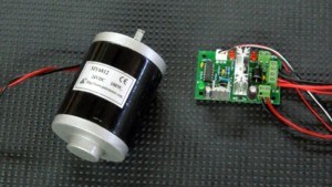
| Prime mover | A 12 V DC gearmotor delivering tens of RPM at torque — a 12 V scooter or wheelchair gearmotor sits in this range | A bare DC motor runs at thousands of RPM (est. ~2,000–4,000) at low torque; the crank wants tens of RPM (est. 40–70) at real torque. The reduction gearbox trades speed for torque: ω_out = ω_in ÷ i, τ_out = τ_in × i × η | jsart110 (Walters); Vol 05 §2 |
| Reduction ratio i | Choose i to land the motor’s natural speed on the crank band, torque to spare | Worked (est.): 3,000 RPM ÷ 60 RPM = i = 50 : 1; τ_out = 0.05 N·m × 50 × 0.75 (η est.) = 1.875 N·m, comfortably over the ~1.2 N·m (est.) hand demand at a 60 mm handle | Vol 05 §2.2; Vol 04 §1 |
| Speed controller | A variable-speed DC drive — in practice a PWM controller (a variable-voltage supply is the sibling alternative) | Sets the RPM and holds it; PWM duty cycle → average voltage → average speed (§6) | jsart110 (Walters); en_31toets (variable-voltage) |
| Power source | A 12 V battery in a separate carrier, fused close to the battery, master switch, conductors sized for stall current | Keeps mass/chemistry out of the case (preserves the hand-cranked weight/balance), and keeps the drive reversible — remove the battery box and refit the handle | jsart110 (Walters) |
| Coupling | Round PU belt in the wheel groove (motor off-axis, adds further reduction) or an 8 mm motor coupling on the wheel’s 8 mm shaft (motor on-axis) | The grooved winding wheel accepts either the hand handle or a motor at one interface; downstream of the wheel nothing changes | jsart129 (Briggs) |
| Set-up target | Set the controller to the RPM that gave the right tempo by hand | Feeder pump rate and take-up/paper speed are locked to the wheel by fixed ratios, so matching one speed matches wind, paper, and tempo at once | Vol 05 §4 |
Table 7-5. Motor-selection guide. The selection problem is a joint speed-and-torque
fit: pick i so a light 12 V motor lands its geared output on the crank’s tens-of-RPM
band with torque over the ~1.2 N·m (est.) hand demand. Motor internals are (est.);
the speed-for-torque relations are exact. Set the tempo by ear — matching the hand tempo
is matching the RPM, no tachometer needed.
7.5.1 PWM operating notes (quick reference)
- PWM sets speed, not torque. Duty cycle → average voltage (V_avg = V_supply × duty) → average speed. At 12 V: 25 % ≈ 3 V, 50 % ≈ 6 V, 85 % ≈ 10 V. Torque comes from the load drawing current at whatever voltage is present; more pulling power means more gearing or a bigger motor, not a lower duty knob (Vol 06 §1.2).
- Low-duty stall floor: ~20–30 % duty
(est.). Below it the average voltage cannot overcome drivetrain stiction and the motor stops; a well-matched gearmotor reaches its slowest wanted tempo above that floor. Starting from rest is the hardest moment (static friction highest) — a brief nudge to higher duty breaks it away (Vol 06 §1.3). - Switching frequency: ≈ 16–25 kHz
(est.). Too low (hundreds of Hz to a few kHz) puts an audible whine under the music; too high slightly cuts effective torque and stresses a marginal controller. On a quiet-mechanism instrument the acoustic requirement is stricter than on a power tool: if the motor sings, raise the frequency (Vol 06 §1.4).
7.6 Automation spectrum
The motor conversion is one point on a continuum from a purely manual instrument to one with no human input during play. Each step removes some effort and gives up some hand-driven character; the axis is a trade, not a ranking.
Table 6 — 6. Automation spectrum
| Level | What it is | Effort removed | Authenticity cost | Source |
|---|---|---|---|---|
| 1 — Hand-crank | Operator turns the crank; one motion raises wind and advances music | None — all effort is manual | None; full hand presence and rubato | Baseline (whole dive) |
| 2 — Motor-assisted crank | 12 V DC gearmotor + PWM control drives the wheel; operator supervises and sets tempo | Muscle effort; involuntary tempo wobble (at fixed duty) | Loses the hand-driven micro-tempo, but a person is still present | jsart110, Ronald Walters (coupling: jsart129, David Briggs) |
| 3 — Automatic roll-player | Self-contained motorised roll box: motor at the top, 4 mm & 8 mm shafts, a solenoid; body 190 × 127 mm (31-note) / 160 × 127 mm (20-note); plays and resets a roll unattended | Muscle and supervision during play | Loses the operator’s live presence; still real pipes and paper | jsart138, Melvyn Wright |
| 4 — MIDI | No paper, no crank; MIDI data drives the valves; a small motor only supplies wind | Muscle, supervision and the physical roll/crank | Furthest from the hand-cranked original; maximal flexibility | en_31toets (medium: Encoding the Music) |
Table 7-6. The automation spectrum. Convenience and self-play rise from Level 1 to Level 4 while authenticity, hand presence, and rubato fall — the two qualities trade against each other along the one axis. A dual-use drive (hand or motor through the one grooved wheel, jsart129) lets the operator choose which end to play from, roll by roll. Rewind is the first job most builds automate: a reversed/geared-up drive (≈ 3:1, jsart61) or simply a cordless screwdriver with a 5 mm hex bit into the Raffin spool’s hex hole (jsart84, Melvyn Wright).
Glossary
Definitions are consistent with the drivetrain glossary in _SOURCE_ANCHORS.md and the
usage across Vols 01–06.
Table 7 — 7. Glossary
| Term | Definition |
|---|---|
| Crank / hand crank | The handle the operator turns; its arm length is the moment arm r for torque (τ = F·r). Removable on many builds for transport — Venable’s arm is 1/8″ × 3/4″ (≈ 3.2 × 19 mm) steel, hitch-pin retained (jsart57). |
| Crank throw | The offset (eccentricity) of a crank pin from the shaft axis; sets the feeder stroke = 2 × throw. Webs ~1/4″ × 1/2″ (≈ 6.4 × 12.7 mm) machined (jsart10) or 50 mm from 20 × 10 mm aluminium bar, M4 bolts (jsart129). |
| Crankshaft | The rotating shaft carrying the throws (and usually the driving wheel), turning in a pair of bearings. Three-lobed, throws 120° apart, for three feeders (Universal/Senior); 8 mm steel in pillow blocks (jsart129), or 3/8″ / 1/4″ steel (jsart57 / jsart88). Turns at only tens of RPM — “RPM minimal” (jsart88). |
| Eccentric | A round disc mounted off-centre on a shaft; a con-rod strap around it converts rotation to reciprocation — mechanically equivalent to a crank throw, with stroke = 2 × disc offset. Slips over an unbroken shaft where a full crank pin is awkward. |
| Connecting rod (con-rod) | The link from a crank throw (or eccentric) to a feeder bellows, converting rotary to reciprocating motion. Hobby versions: 4 mm brass rod (jsart129), No. 6 aluminium knitting needles in hardwood tops (jsart80); dry-lubricated with talc or graphite (jshints). |
| Driving wheel / drive wheel | The wheel on the crankshaft that transmits drive to the music transport — via a friction tyre, an abrasive-faced pulley, or a grooved wheel + round cord. Doubles as the winding wheel and a modest flywheel; 17 mm Formply with a groove “for a motor drive” (jsart129). |
| Idler wheel | An intermediate friction wheel between the driving wheel and the take-up spool; a ≈ 2 7/8″ (≈ 73 mm) disc with a 3″-OD O-ring tyre on a 1/4″ shaft (jsart57). It bridges the gap and sets the direction of rotation, but — being a simple single-diameter wheel — its diameter cancels from the crank-to-take-up ratio R, which is set by the driving-wheel and take-up-wheel diameters alone. |
| Take-up spool / winding reel | The spool that winds the played paper and pulls the roll past the tracker bar; ≈ 100 mm-dia PVC drum on the Höffle (en_bouwhoeffle), 8 mm shaft (jsart129). Its effective diameter grows as paper winds on (the tempo-creep source). |
| Drive cord / drive belt | Round polyurethane (“polyamide”) belting, 4–5 mm dia, heat-welded into a loop, running in the wheel grooves to the music spool (jsart120); the “Drive cord 5 mm” of the Höffle parts list (en_materiaal). |
| Friction clutch | A spring-loaded slipping contact (inner-tube tyre + clutch spring, jsart80; spring-pressed pin coupling, en_20Hoffle2) that transmits take-up drive yet slips for hold, end-of-roll, and rewind — and limits paper tension. |
| Gear ratio | The speed multiplier of a gear or pulley pair: ω_out = ω_in × (T_driver ÷ T_driven); torque inversely, τ_out = τ_in × (T_driven ÷ T_driver) × η. 1:1 right-angle drive (jsart88); ~3:1 rewind (jsart61). |
| Torque | Rotational effort, τ = F · r (tangential force × moment arm); the handle length sets the mechanical advantage between hand and shaft; units N·m. |
| Flywheel | A rotating mass storing kinetic energy (E = ½·I·ω²) to smooth a pulsating (lumpy) torque so the crank turns evenly and the tempo stays steady. No source specs a dedicated one — the heavy winding/driving wheel serves as a modest flywheel (principle; any inertia (est.)). |
| Gearmotor | A DC motor with a reduction gearbox giving low output RPM at high torque — matching the slow crank; ω_out = ω_in ÷ i, τ_out = τ_in × i × η. The eBay “experimental gearmotor” / 12 V scooter motor of the conversion (jsart110). |
| PWM (pulse-width modulation) | Fast on/off switching of the DC supply whose duty cycle sets the average voltage (V_avg = V_supply × duty) and therefore the average motor speed. The “variable speed control” of the conversion (jsart110); sets speed, not torque. |
7.7 Cross-index
7.7.1 Topics to volumes (Vols 01–06)
Table 8 — 8.1 Topics to volumes (Vols 01–06)
| Topic | Where developed |
|---|---|
| The thesis — one rotation, two jobs; the shared shaft; the organ-grinder tradition | Vol 01 §2–§4 |
| Scale names (20 = Carl Frei/Raffin, 26 = Alderman, 31 = Raffin/Höffle); note count ≠ pipe count; roll widths (110/140 mm) | Vol 01 §5 |
| Crank throw, crankshaft, con-rods; stroke = 2 × throw; built-up crank construction | Vol 02 |
| Driving wheel, idler, take-up spool, friction clutch; the three drive forms | Vol 02 |
| Crank turns slowly (“RPM minimal”, est. 40–70) | Vol 01 §4; Vol 03 §1 |
| Tempo = π·d·n ÷ s; tempo ∝ crank RPM; the worked RPM-tempo table | Vol 03 §2 (and Table 7-2) |
| Take-up-diameter tempo creep; why the friction clutch tames it; steady cranking as a skill | Vol 03 §3–§4 |
| τ = F·r; the handle as a lever / mechanical advantage | Vol 04 §1 |
| Gear/pulley law; jsart88 1:1 and jsart61 ~3:1 checks; power conserved (× η) | Vol 04 §2 (and Table 7-3) |
| What makes an organ hard to crank — the lumpy feeder load, pressure × area, friction | Vol 04 §3 |
| The flywheel / heavy winding wheel; the reservoir’s pneumatic half | Vol 04 §4 |
| The documented 12 V conversion; why a gearmotor; coupling at the grooved wheel; speed-matching | Vol 05 |
| PWM (duty → voltage → speed); stall floor; whine-vs-torque frequency | Vol 06 §1 |
| Motorised rewind; the automation spectrum; authenticity-vs-convenience | Vol 06 §2–§4 (and Table 7-6) |
7.7.2 Topics to sibling dives (cross-ref, not re-derived here)
Table 9 — 8.2 Topics to sibling dives (cross-ref, not re-derived here)
| Sibling dive | Owns (this dive defers to it) |
|---|---|
| Wind Systems | Feeder bellows, reservoir, sprung spill valve, regulation, leaks, the ~5 in H₂O (127 mm ≈ 1.245 kPa) working pressure. This dive owns only the crank → con-rod → feeder linkage and how bellows load makes the organ hard to crank. |
| Encoding the Music | The paper roll and cardboard book medium, tracker-bar hole map, 110 / 140 mm roll widths, beat spacing s, MIDI note map. This dive owns only the crank → driving wheel → take-up transport that pulls it. |
| The Case, Façade & Figures (Dive 11) | The moving-figure linkages (cam / eccentric / bell-crank to monkey, bird, bandmaster). This dive marks the take-off on the crankshaft and stops. |
| How Organ Pipes Make Sound | Pipe voicing and the acoustics of the sounding tubes; how much air a rank draws (which sets how hard the wind side is to crank). This dive references pipe air-demand only as a load. |
| The John Smith Universal Organ (Dive 5) | The worked Universal/Senior build. Shared drive numbers kept identical: three feeders on a 120° crankshaft, friction/idler/take-up drive, ~5 in H₂O. This dive is the cross-cut “drive” reading of it. |
| The Hobby Crank Organ (Dive 8) | The worked Höffle build. Shared numbers: 110 mm paper, ≈ 100 mm PVC take-up drum, 5 mm drive cord, sprung pin-clutch coupling. |
| Fairground & Dutch Street Organs (Dive 14) | Grand-machine drive — spring/clockwork motors, large electric drives, self-playing fairground mechanisms. This dive touches those as context only. |
7.8 Bibliography
7.8.1 melright.com/busker — the John Smith Busker/Senior/Universal contributor anthology
Cited by article + author (© Melvyn Wright and individual contributors). The pages sit
on a self-signed TLS certificate; fetch with curl -sk http://www.melright.com/busker/PAGE.htm.
Article index: jsmenu.htm.
Table 10 — 9.1 melright.com/busker — the John Smith Busker/Senior/Universal contributor anthology
| Article | Author | Topic |
|---|---|---|
| jsart05 | John Smith / Melvyn Wright | John Smith Senior 20 overview — 20-note scale, 140 mm rolls (the organ jsart110 motorises) |
| jsart10 | Noel Maw | Making the tracker bar and crankshaft without welding; “model engineering and organ building have so much in common” |
| jsart15 | Charles Darley | Filing the central groove in the drive/clutch wheels (200 mm round file in a jig) — the grooved-wheel + cord drive form |
| jsart57 | Wallace Venable | Alternative Drive Construction — the clearest whole-drive-train account: two-piece crankshaft, wood drive wheel with pin drive, ≈ 73 mm O-ring idler, brass-bushed shafts, removable hand crank |
| jsart61 | Wallace Venable | Gear-Driven Rewind Mechanism — a gear pair “with a nice ratio of about 3:1” for fast unloaded rewind (the ~3:1 case) |
| jsart80 | Dennis Spinks | Alternative Friction Wheel and Lid Spring — inner-tube-tyre friction drive + clutch spring; “build up the drive-spool tyre” to speed the drive; knitting-needle con-rods |
| jsart84 | Melvyn Wright | Hand and Motorised Rewind — cordless screwdriver + 5 mm hex bit into the Raffin spool’s hex hole; hinged bearing |
| jsart88 | Dwayne Glanton | Relocating the Busker Hand Crank — two 90° nylon miter gears (30:30 = 1:1); “the RPM of the crankshaft is minimal” |
| jsart110 | Ronald Walters | Motorising the John Smith Senior Organ — the motor-conversion anchor: 12 VDC motor + variable-speed DC drive + separate 12 V battery; motorised rewind; eBay parts |
| jsart120 | Melvyn Wright | Making Polyurethane Drive Belts — round PU belting, “most organ builders use 4 mm or 5 mm,” heat-welded into a loop |
| jsart129 | David Briggs | Built-Up Crank, Glass Lid and Winding Handle — 50 mm bolted aluminium webs on 8 mm steel; winding wheel with a groove “for a motor drive” and an “8 mm motor coupling” (the coupling anchor) |
| jsart138 | Melvyn Wright | Making an Automatic Roll-Player (work in progress) — motorised roll box: motor + solenoid, 190 × 127 mm (31-note) / 160 × 127 mm (20-note) |
| jshints | Charles Darley / Melvyn Wright | Improved Driving Wheel, Con-Rod Lubricant — talc/graphite dry lube; P80 abrasive high-grip driving-wheel face |
7.8.2 hobbycrankorgan.com — Walter Höffle’s 20-note and 31-note builds
(Dutch original at hobbydraaiorgel.nl, same subdirectory; swap en_ for the Dutch
page name.)
Table 11 — 9.2 hobbycrankorgan.com — Walter Höffle's 20-note and 31-note builds
| Page | Topic |
|---|---|
| en_materiaal | Parts/materials list for the 20-note Höffle — “Drive cord 5 mm” (confirms the 5 mm round drive cord); membrane leather < 0.5 mm; PVC hose 4 mm ID / 6 mm OD |
| en_bouwhoeffle | The 20-note build — 110 mm paper; the winding reel is a 100 mm-diameter PVC tube with plywood end discs (the take-up drum diameter) |
| en_20Hoffle2 | The crank-to-take-up coupling — two interlocking pins with a small spring pressing the transfer wheel against the rear wall (a friction clutch always present) |
| en_31toets | The 31-note build — MIDI-driven option (cross-ref Encoding/MIDI); documents a variable-voltage DC supply to vary a small motor’s speed (the speed-vs-voltage principle) |
7.8.3 General engineering references (formulas verified independently)
- Gear ratio / speed / torque — standard machine design (Shigley; engineeringtoolbox.com): output speed = input speed × (driver teeth ÷ driven teeth); torque inversely. Verified against jsart88 (30:30 = 1:1) and jsart61 (~3:1).
- Torque = force × radius (τ = F·r) — standard statics.
- DC motor PWM speed control — general motor-driver references (DroneBot Workshop; Bodine Electric low-voltage PWM controls): PWM sets the average armature voltage → average speed; a ~20–30 % minimum duty stall floor; a gearbox trades speed for torque (τ up, ω down by i × η). Consistent with the jsart110 recipe.
7.8.4 Plans (owned-document sources)
- johnsmithbusker.co.uk (
/busker.html) and rollcutter.com — the John Smith plan pages. Numeric crank/drive dimensions live in the purchased plan packet; treat plan-only figures as(est.)unless a melright article restates them.
7.9 One-line summary
A hand-cranked busker organ is one slow rotary input (est. 40–70 RPM) split by one shaft into wind (throws → con-rods → feeders, stroke = 2 × throw) and music (driving wheel → idler → take-up spool through a slipping friction clutch); tempo = π·d·n ÷ s ∝ crank RPM; speed and torque trade inversely through any ratio and never add power; the heavy winding wheel is a modest flywheel and the reservoir smooths the wind; and the whole hand can be replaced by a 12 V gearmotor + PWM drive + 12 V battery (jsart110) coupled at the same grooved wheel (jsart129), set to the RPM that gave the right tempo by hand — one point on a spectrum that runs to a self-playing roll box (jsart138) and MIDI (en_31toets), trading effort for authenticity at every step.
Comments (0)