Turning The Crank · Volume 2
Turning the Crank — Vol 02: The Crank & Drivetrain
Vol 01 established the thesis: one turn of the handle does two jobs at once — it raises the wind and it advances the music — and it does them through a single rotating shaft. This volume takes that shaft apart. It is the mechanics core of the dive: every part named, its job stated, and the hobby material or dimension that hobby builders actually use to make it, cited to the melright.com/busker contributor articles and the hobbycrankorgan.com build pages.
The order of the tour follows the flow of motion. Rotary motion enters at the hand crank, is carried by the crankshaft, is split there into two branches, and leaves as two very different kinds of work. On the wind branch the crankshaft’s throws swing connecting rods that pump the feeder bellows — rotary motion becoming reciprocating (back-and-forth) motion. On the music branch a driving wheel on the same shaft transmits drive through a friction tyre, a drive cord, or a gear-and-pin coupling, by way of an idler, to the take-up spool that pulls the paper roll past the tracker bar — rotary motion staying rotary but slowed, redirected, and slip-limited. The naming chain this volume must keep straight, end to end, is: crankshaft → crank throw → driving wheel → idler (tyre) → take-up spool, with a friction clutch on the take-up and connecting rods hanging off the throws.
Two boundaries are held throughout. The bellows themselves — leathering, reservoir, spill valve, the ~5 in H₂O working pressure — belong to Wind Systems; this volume owns only the crank-to-feeder linkage. The paper roll and book medium the take-up spool pulls — hole map, roll widths, tracker bar — belong to Encoding the Music; this volume owns only the transport that moves it. And a third take-off exists that is only pointed at: the moving figures (monkey, bird, bandmaster) are driven from cams and cranks on this same crankshaft, but their linkages belong to The Case, Façade & Figures (Dive 11). Mention the take-off point, cross-ref, do not re-derive.
2.1 The whole train at a glance
The drivetrain is best read as a capital-T: one horizontal shaft with two branches dropping off it. The diagram below labels every part this volume builds, in the two-branch layout that the rest of the volume follows part by part.
Figure 2-1. The complete drivetrain. One crankshaft carries three throws that work three feeder bellows through connecting rods (the wind branch), and a driving wheel that reaches the take-up spool through an idler and a friction clutch (the music branch). The figures are cammed off the same shaft but are Dive 11’s subject. Layout after the whole-drive descriptions of jsart57 (Wallace Venable), jsart129 (David Briggs), jsart80 (Dennis Spinks), and en_20Hoffle2.
2.2 The hand crank
The prime mover is the operator’s arm, and its interface to the machine is the hand crank — a handle on an arm fixed to one end of the crankshaft. Two design points matter here (a third, mechanical advantage, is Vol 4’s). First, the arm length is the moment arm: the further the grip sits from the shaft axis, the less hand force is needed for the same shaft torque, so the handle radius is not arbitrary — it is chosen for a comfortable turning effort against the bellows load. Second, on most builds the crank is removable for transport: Venable makes the crank arm from 1/8″ × 3/4″ (≈3.2 × 19 mm) steel and retains it with a hitch-pin so it lifts off (jsart57, Wallace Venable), and Briggs mounts his winding handle on an 8 mm motor coupling on the driving/winding wheel so the same interface takes either the hand crank or, later, a motor (jsart129, David Briggs). The crank does not merely spin the shaft; it is the removable, human end of a chain whose other end is the punched paper. Where builders want the handle at the side of the case rather than on the shaft end, a right-angle drive is added (a 1:1 miter-gear pair — jsart88, Dwayne Glanton — treated with the other drive forms below and in Vol 3).
2.3 The crank throw
Everything the wind branch does begins with the crank throw — the offset, or eccentricity, of a crank pin from the axis of the shaft. A pin set a distance e away from the shaft centreline traces a circle of radius e as the shaft turns. A connecting rod hung on that pin is therefore pulled and pushed along its length by an amount that depends only on e, not on the length of the rod: the pin moves from e on one side of the axis to e on the other, so the total travel — the stroke — is exactly twice the throw.
stroke = 2 × throw. Doubling the throw doubles the feeder’s swept stroke; halving it halves the wind delivered per revolution. The throw is the single geometric number that sets how much air each feeder pumps per turn of the handle.
The stroke matters directly to Wind Systems, because feeder displacement per revolution is (roughly) feeder area × stroke, and stroke is fixed here at the crankshaft. What this volume owns is how the throw is made. Two hobby recipes recur.
The first is John Smith’s own machined-web approach as restated by Noel Maw: build the crankshaft up from webs (the flat cheeks that carry the pin off the axis) rather than machining it from solid, and make those webs about 1/4″ (≈6.4 mm) thick and about 1/2″ (≈12.7 mm) deep so there is enough metal to braze or bolt the pin and journals securely (jsart10, Noel Maw). Maw’s oft-quoted line — “model engineering and organ building have so much in common” — lands exactly here: the throw is a small model-engineering part.
The second is David Briggs’s fully built-up, non-welded web: cut the webs 50 mm long from 20 × 10 mm aluminium flat bar and clamp them to the shaft and pins with M4 bolts (jsart129, David Briggs). No brazing torch, no lathe work on a hardened billet — just bar stock, a drill, and bolts. The distance from the shaft hole to the pin hole in that 50 mm web is the throw, and it is set at drilling time.
There is a mechanically equivalent alternative worth naming because it appears in the wider organ-building literature even where the hobby articles favour a true crank: the eccentric. An eccentric is a round disc mounted off-centre on the shaft, encircled by a strap (a split collar) that carries the con-rod; as the shaft turns, the disc’s off-centre profile drives the strap back and forth exactly as a crank pin drives a con-rod, with the offset of the disc’s centre playing the role of the throw. Its advantage is that it can be slipped over an unbroken shaft — no need to build the shaft up around a pin — which is why it is reached for where a full crank web is awkward. The stroke rule is identical: stroke = 2 × (disc offset). In the small busker drivetrain the built-up crank web usually wins on simplicity and cost, but the eccentric is the same idea wearing a different shape.
Figure 2-2. The crank throw and the stroke it produces. The pin sits a distance e (the throw) off the shaft axis; over half a revolution it moves from top to bottom of its circle, a travel of 2e*. Web dimensions after jsart10 (Noel Maw, 1/4″ × 1/2″ machined webs) and jsart129 (David Briggs, 50 mm webs from 20 × 10 mm aluminium bar).*
2.4 The crankshaft
The crankshaft is the horizontal spine that carries the throws (and usually the driving wheel) and turns in a pair of bearings. Its defining feature on the larger organs is that it is three-lobed, with the three throws set 120° apart, one for each of the three feeders on the Universal and Senior 20 (JS Universal brief; cross-ref Wind Systems). The 120° stagger is not decoration: it phases the three feeders so that as one reaches the bottom of its compression stroke another is mid-stroke and a third is on its near-free return, so at least one feeder is always delivering. The raw wind into the reservoir is therefore far smoother than a single feeder could give — the reason the wind-hungry valved organ carries the extra two throws. (The Basic 20 uses just two feeders on a two-throw shaft, 180° apart, alternating; the wind ripple is the topic Wind Systems owns.)
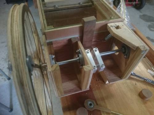
For the shaft itself the hobby consensus is a plain steel rod running in cheap bearings. Briggs uses 8 mm steel rod in eBay pillow-block bearings (jsart129, David Briggs). Wallace Venable’s alternative drive uses 3/8″ (≈9.5 mm) steel brazed through three bearings, with the front throw made removable so the drive wheel can be pulled (jsart57, Wallace Venable). Dwayne Glanton’s crank relocation runs a 1/4″ (≈6.4 mm) crankshaft (jsart88, Dwayne Glanton). The range is narrow — roughly a quarter- to three-eighths-inch rod — and the reason it can be so modest is speed: the crankshaft turns at only tens of RPM. Glanton states it plainly — “since the RPM of the crankshaft is minimal, steel should make a good bearing” (jsart88) — which is why unhardened steel journals in nylon or brass bushes last indefinitely here. (No source gives a crank speed in rev/min; Vol 3 treats it as (est.) ≈ 40–70 rev/min and never as a sourced figure.)
Because the throws must be offset from the shaft axis, a one-piece crankshaft has to be either machined from oversized stock or built up from pieces, and the hobby strongly favours building up. Two non-welded methods appear above: Maw’s brazed machined webs (jsart10) and Briggs’s fully bolted 50 mm aluminium webs on M4 bolts (jsart129). Venable’s is a hybrid — a two-piece crankshaft whose main shaft is brazed through the bearings while the front throw is removable, so the drive wheel and its throw come off as a unit for service (jsart57). All three avoid the welding heat that would warp a slender rod and throw the journals out of line.
Alignment is the whole game in a built-up crankshaft, and it is why the hobby methods are jigged rather than eyeballed. The three (or two) journals and the main bearings must be coaxial to a few tenths of a millimetre, or the shaft binds in its pillow blocks and the con-rods bend on every revolution; the throws, in turn, must all present the same radius or the feeders will not share the load evenly. Building up from bar and bolts (jsart129) lets the maker drill matched holes in a stack of identical webs so every throw is the same, then assemble on a straight rod — the model-engineering discipline Maw invokes. The slow speed forgives a great deal here: at tens of RPM a crankshaft that would scream at engine speeds runs silently, and a small residual misalignment shows up only as a little extra cranking effort, not as vibration or wear. This tolerance for rough-and-ready fabrication is exactly why the busker drivetrain is buildable on a kitchen-table toolset.
2.5 The connecting rods to the feeders
The connecting rods — con-rods — are the links that turn the crank throws’ circular motion into the straight push-pull the feeder bellows need. Each rod runs from a journal on a throw down to the top board of one feeder; as the throw sweeps its circle, the rod’s lower end reciprocates through the stroke (2 × throw) set at the crankshaft. This is the classic slider-crank of every reciprocating engine, run in reverse — here the crank drives the “piston,” not the other way about.
The hobby versions are deliberately light and cheap, because the loads are small and the speed low. Briggs makes the con-rods from 4 mm brass rod, tapped into 8 mm hardwood tops that carry a 6 mm-bore bearing pressed in to ride the throw journal (jsart129, David Briggs). Dennis Spinks reaches for the household parts bin and makes his con-rods from No. 6 aluminium knitting needles set into hardwood tops — a trick he has used on his Busker, Senior, and Universal 26 alike (jsart80, Dennis Spinks). The common thread is a hardwood bearing block at the crank end riding on the steel or brass journal, and the friction there is managed not with oil (which would migrate onto leather and card) but with a dry lubricant: Charles Darley uses talcum powder, a naturally slippery, “Teflon-like” film on wood, and Melvyn Wright notes graphite is better still (jshints, Charles Darley). A dry-lubricated hardwood-on-steel journal at tens of RPM is effectively a lifetime bearing.
What the con-rods deliver — the feeders, their leathering, the reservoir they charge, and the ~5 in H₂O they hold — is the subject of Wind Systems. This volume stops at the feeder top board. The one number to carry across the boundary is the stroke, and the stroke is set by the throw, above.
2.6 The music branch: the driving wheel
The second branch leaves the crankshaft through the driving wheel (also called the drive wheel), a disc fixed on the shaft that transmits the crank’s rotation onward to the music transport. It is the most variable part of the whole train, because there are three quite different ways hobby builders get drive from it to the next wheel, and the choice sets how the take-up behaves. All three share one job — carry rotation from the driving wheel to an idler and thence to the take-up spool — but they differ in grip, in slip, and in how the tempo is trimmed.
The driving wheel also earns a second title. On many builds it is the same disc the operator’s winding handle attaches to, and it is deliberately heavy — Briggs cuts his from 17 mm Formply and fits the handle with an 8 mm motor coupling, noting that “the groove in the wheel is for a motor drive” (jsart129, David Briggs). A heavy driving/winding wheel doubles as a modest flywheel, storing energy on the easy part of each crank cycle and giving it back on the lumpy part; that smoothing is Vol 4’s subject, but the part that does it lives here. The motor-drive groove is the seam that lets the same wheel take either a hand crank or a motor belt — the coupling detail Vol 5 builds on.
2.6.1 Friction-tyre drive
The simplest drive is friction: face the driving wheel (or the idler) with a rubbery tyre and press it against the next wheel so surface grip carries the rotation. Hobby tyres are salvage parts — an inner-tube band, an O-ring, or a vacuum-cleaner drive belt stretched over the rim (jsart57, Wallace Venable; jsart80, Dennis Spinks). Where more grip is wanted, Charles Darley glues 3M P80 “Premium Paint Removal” coarse abrasive to a card drive pulley (a diagonal joint so the seam does not thump), turning the wheel face into a high-grip friction surface (jshints, Charles Darley) — the friction wheel needs grip, not merely contact.
The friction drive carries one important tempo lever. Spinks points out that one can build up the drive-spool tyre by adding three or four layers of inner tube to speed up the drive (jsart80): a larger effective drive diameter turns the take-up faster for a given crank speed, so more paper passes per turn of the handle. That is the mechanism behind the RPM-to-tempo relationship Vol 3 works out — a change made here at the tyre, not in any gear.
2.6.2 Grooved wheel and round drive cord
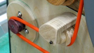
The second drive form replaces surface friction with a positive-ish belt in a groove. A central groove is cut into both the driving wheel and the take-up (or clutch) wheel — Darley files his with a 200 mm round file in a jig (jsart15, Charles Darley) — and a round drive cord runs in the two grooves like a tiny V-belt. The cord is round polyurethane belting (sold as “polyamide” or polyurethane round belt), which Melvyn Wright notes is “used extensively in hand-turned organs, usually to transmit the drive to the music spools”; most organ builders use the 4 mm or 5 mm diameter belting, cut to length and heat-welded end to end into a loop (jsart120, Melvyn Wright). The hobbycrankorgan 20-note parts list confirms the same size from the other direction — a plain “Drive cord 5 mm” (en_materiaal). A welded PU loop in a filed groove is quiet, forgiving of shaft-centre error, and slips cleanly under overload rather than jamming.
2.6.3 Gear or pin coupling
The third form is positive drive — teeth or pins that cannot slip in normal running. Glanton relocates the hand crank to the side of the case with two 90° nylon miter gears (McMaster-Carr #7297K16: molded nylon, 20° pressure angle, 24 diametral pitch, 30 teeth, 1.25″ pitch diameter, 1/4″ bore), a 30-to-30 = 1:1 right-angle drive that changes direction but not speed (jsart88, Dwayne Glanton). Hobbycrankorgan’s take-up coupling is a simpler positive form still — two interlocking pins, one on the winding-reel shaft and one on the large transfer wheel, that drive each other directly (en_20Hoffle2). Positive drives do not creep, but on the take-up they must be paired with slip somewhere, which is the job of the clutch below.
Figure 2-3. Three ways to get drive off the driving wheel. Friction tyre (grip, inherent slip), grooved wheel with a round PU cord (belt, gentle slip under overload), and gear or pin coupling (positive, no slip — so it needs a clutch on the take-up). Sources as marked.
2.7 The idler wheel
Between the driving wheel and the take-up spool most builds interpose an idler wheel — an intermediate friction wheel that carries the drive across the gap between them. Venable’s is the best-specified example: a 2 7/8″ (≈73 mm) disc cut with a 3″ hole saw, grooved and fitted with a 3″-OD O-ring as a tyre — the O-ring being a hydraulic-cylinder repair part pressed into service — running on a 1/4″ (≈6.4 mm) idler shaft in brass bushes (jsart57, Wallace Venable). A simple idler bridges the driving wheel to the take-up and fixes the direction of rotation, but — a standard result — its own diameter cancels from the overall ratio: the same rim speed enters and leaves it, so the crank-to-take-up speed ratio is set by the driving-wheel and take-up-wheel diameters alone, not by the idler’s. Vol 3 makes that ratio explicit.
2.8 The take-up spool
The take-up spool — the winding reel — is where the music branch does its useful work: it winds on the played paper and, in doing so, drags the roll off its supply spool and past the tracker bar. The Höffle 20-note build makes the take-up reel a 100 mm-diameter PVC tube with plywood end discs (en_bouwhoeffle), a concrete drum diameter that feeds directly into the paper-speed arithmetic Vol 3 works out. Briggs runs his take-up on an 8 mm shaft in pressed-in bearings, the same bearing recipe as the crankshaft (jsart129, David Briggs).
The take-up drum has one consequence worth flagging here even though its effect belongs to Vol 3: its effective diameter grows as paper winds onto it. With a rigid drive ratio, a growing drum would pull paper faster and faster through a roll, so the tempo would creep upward from start to end. The mechanism that absorbs that — and that lets the operator, not a gear number, govern the tempo — is the friction clutch. What the take-up actually pulls — the 110 mm and 140 mm paper rolls, the hole map, the tracker bar it drags the paper across — belongs to Encoding the Music; that dive explicitly defers the transport mechanics to this one.
2.9 The friction clutch
The friction clutch is the part that makes the take-up practical. The take-up must be driven while the organ plays, so the paper advances; but it must be able to slip when the paper is held, when a roll reaches its end, and when the operator rewinds — otherwise the drive would tear the paper or stall the crank. A clutch that always transmits some torque but lets go past a threshold does all three.
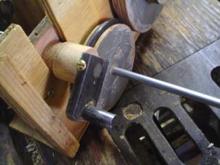
Spinks builds the friction clutch from an inner-tube tyre on the drive spool engaged by a clutch spring, and reports it “gives great torque, far more than is needed” (jsart80, Dennis Spinks) — the spring sets the slip threshold, and because the take-up load is tiny, there is torque to spare. Hobbycrankorgan reaches the same end with a positive coupling plus a designed-in slip: the two interlocking pins drive the winding reel, while a small spring presses the transfer wheel against the rear wall so a friction clutch is always present (en_20Hoffle2). Either way the result is the same — drive with a built-in slip limit. That slip is what turns the growing-drum tempo creep from a problem into a non-issue: the paper speed can be governed by the tracker-bar drag and the operator’s steady hand rather than being forced by a rigid ratio (the tempo story is Vol 3’s; the effort and torque story, including why a clutch that gives “far more torque than needed” is the right call, is Vol 4’s).
2.10 Naming the chain, part by part
Collected in one place, with the job of each part and the hobby material or dimension that makes it, the drivetrain is the following. Every figure keeps its source-original imperial value with a metric equivalent added; anything no source states is flagged (est.).
Table 1 — Naming the chain, part by part
| Part | Function | Hobby material / spec | Source |
|---|---|---|---|
| Hand crank | Operator’s input; arm length is the moment arm for torque | Removable arm, 1/8″ × 3/4″ steel, hitch-pin retained (jsart57); handle on 8 mm motor coupling (jsart129) | jsart57, jsart129 |
| Crank throw | Offsets the pin off-axis; sets feeder stroke = 2 × throw | Machined webs ~1/4″ × 1/2″ (jsart10); built-up webs 50 mm from 20 × 10 mm Al bar, M4 bolts (jsart129) | jsart10, jsart129 |
| Crankshaft | Carries the throws and driving wheel; splits the two branches | 8 mm steel in pillow blocks (jsart129); 3/8″ (≈9.5 mm) two-piece (jsart57); 1/4″ (≈6.4 mm) (jsart88); three throws 120° apart | jsart129, jsart57, jsart88 |
| Connecting rod | Turns throw rotation into feeder reciprocation | 4 mm brass rod in 8 mm hardwood tops, 6 mm-bore bearing (jsart129); No. 6 Al knitting needles (jsart80); dry lube talc/graphite (jshints) | jsart129, jsart80, jshints |
| Driving / winding wheel | Transmits crank drive to the music branch; doubles as flywheel | 17 mm Formply, groove “for a motor drive,” 8 mm coupling (jsart129) | jsart129 |
| Friction tyre | Grip surface carrying drive by friction | Inner tube / O-ring / vacuum belt (jsart57, jsart80); P80 abrasive face (jshints); build up to speed the drive (jsart80) | jsart57, jsart80, jshints |
| Drive cord | Round belt in filed grooves to the spool | Round PU belting 4–5 mm, heat-welded loop (jsart120); “Drive cord 5 mm” (en_materiaal) | jsart120, jsart15, en_materiaal |
| Idler wheel | Bridges the gap to the take-up; sets direction (its own diameter cancels from the ratio) | 2 7/8″ (≈73 mm) disc + 3″-OD O-ring tyre, 1/4″ shaft (jsart57) | jsart57 |
| Take-up spool | Winds played paper, pulls the roll past the tracker bar | ≈100 mm-dia PVC drum (en_bouwhoeffle); 8 mm shaft (jsart129) | en_bouwhoeffle, jsart129 |
| Friction clutch | Transmits take-up drive yet slips for hold / rewind | Inner-tube tyre + clutch spring (jsart80); spring-pressed interlocking-pin coupling (en_20Hoffle2) | jsart80, en_20Hoffle2 |
Read as a chain, the drive is: the hand crank turns the crankshaft; the crankshaft’s crank throws swing the connecting rods that pump the feeder bellows (the wind branch, handed to Wind Systems); and the crankshaft’s driving wheel reaches, through a friction tyre or a drive cord or a gear/pin coupling and by way of the idler, the take-up spool, which is driven through a friction clutch so it pulls the paper but slips on hold and rewind (the music branch, handed to Encoding the Music). The figures are cammed off the same shaft and handed to Dive 11.
2.11 What the next volumes build on this
This volume fixed the parts and the geometry; the three that follow turn them into behaviour. Vol 3 (Speed, RPM & Tempo) takes the take-up drum diameter (≈100 mm), the crank-to-take-up ratio set by the driving-wheel and take-up-wheel diameters, and the tyre-build-up trick, and works out how crank RPM maps to musical tempo — and why the growing drum and the friction clutch mean the operator’s steady hand is the real tempo control. Vol 4 (Torque, Effort & the Flywheel) takes the crank-handle moment arm, the lumpy per-cycle feeder load delivered through the con-rods, and the heavy Formply driving wheel, and shows how the wheel-as-flywheel and the reservoir together smooth the crank. Vol 5 (Electric-Motor Drive) takes the one seam this volume flagged — the driving wheel’s motor groove and 8 mm motor coupling (jsart129) — and couples a 12 V gearmotor to the same wheel the hand crank uses (jsart110, Ronald Walters), so that matching one speed keeps the fixed bellows and take-up ratios, and therefore the designed tempo, intact. The parts are the same; only the prime mover changes.
Comments (0)