Turning The Crank · Volume 3
Turning the Crank — Vol 03: Speed, RPM & Tempo
This volume follows the one quantity the operator controls with a bare hand and nothing else: how fast the crank turns. Vol 02 traced the drivetrain part by part — crank throw, crankshaft, con-rods to the feeder bellows on one branch, and the driving wheel → friction tyre / drive cord → idler → take-up spool on the other. This volume takes that same mechanism and asks the musical question: given a crank turning at some rate, what tempo comes out of the organ, and why is holding that tempo steady a genuine skill rather than a triviality?
The short answer is a single exact relationship — musical tempo is proportional to crank speed — wrapped in a nest of practical caveats: the crank turns surprisingly slowly, no hobby source pins down the exact millimetres of paper advanced per turn, the take-up drum’s diameter changes as the roll winds on, and a human arm is a poor speed governor. The exact physics is developed in §2; the drum-diameter drift in §3; and the human-factors headline — the reason a flywheel and the wind reservoir both earn their keep — in §4. Torque, effort, and the flywheel’s mechanics are Vol 04’s subject; this volume only names them where they bear on holding tempo. The roll medium, the beat spacing punched into it, and the note scales all belong to Encoding the Music, cross-referenced where the paper’s geometry sets the tempo.
Voice / units / sourcing note. Rotational rates are given in rev/min (RPM) and rev/s, linear paper speeds in mm/min and mm/s, and tempo in beats per minute (BPM). The tempo relationship v = π·d·n and BPM = π·d·n ÷ s is derived and stated exactly. Every illustrative input to a worked example — crank RPM, take-up diameter, beat spacing — is marked (est.), because no hobby source states these numbers. The one hard sourced fact about crank speed is a qualitative one: jsart88 (Dwayne Glanton) records that “the RPM of the crankshaft is minimal.” No page gives a figure, so any number here is an estimate and is flagged as such.
3.1 The crank turns slowly
The first thing that surprises a builder coming from powered machinery is how slowly a busker organ’s crankshaft actually rotates. It looks busy — three con-rods reciprocating, feeders slapping, a paper roll creeping past the tracker bar, perhaps a figure nodding — but the shaft carrying all of that turns at a walking pace.
The only direct statement in the hobby corpus is qualitative. In the course of relocating a Busker’s hand crank onto two right-angle nylon miter gears, Dwayne Glanton notes that steel would serve perfectly well as a bearing material for the crankshaft “since the RPM of the crankshaft is minimal” (jsart88, Dwayne Glanton). That is the load-bearing fact: the crankshaft turns slowly enough that even a crude steel-on-steel bearing will outlast the organ. It does not give a number, and no other melright/busker or hobbycrankorgan page does either.
From playing experience across the hobby, a comfortable musical tempo corresponds to a crank turning at roughly 40–70 rev/min (est.) — call it about one revolution per second (est.) as a round mental anchor. At 60 RPM the crank makes one full turn every second; at 40 RPM, one turn every 1.5 s; at 70 RPM, a little more than one turn per second. These are estimates offered to make the arithmetic in §2 concrete, not sourced values, and they are marked (est.) every time they appear. The point that is sourced is the order of magnitude: tens of RPM, not hundreds (jsart88).
Two consequences follow immediately and are worth stating before the tempo math:
- The whole drive is designed around a slow input. A bare DC motor spinning at thousands of RPM cannot simply be bolted on; matching this tens-of-RPM regime is the entire problem an electric conversion has to solve (that is Vol 05’s subject — the documented 12 V gearmotor recipe of jsart110). Here it only explains why the hand-crank numbers are so small.
- A slow shaft is an unforgiving tempo reference. At ~1 rev/s the operator has very few “samples” per second to average against. A momentary slow-down of a quarter-turn is an audible tempo dip, because a quarter-turn is a meaningful fraction of the beat. This is the seed of the human-factors problem in §4.
Everything downstream — bellows pump rate, paper speed, tempo — is geared down or sideways from this slow crank (Vol 02): the take-up spool typically turns slower still, and the feeders pump once per feeder per revolution. Nothing in the machine runs fast.
3.2 The tempo relationship
Musical tempo on a paper-roll organ is not set by a metronome, a clock, or an escapement. It is set by how fast the paper travels past the tracker bar, because the music is encoded as a pattern of slots and bridges along the length of the paper. Move the paper faster and the same encoded pattern is read out faster — the tune speeds up. The chain from the operator’s hand to the perceived tempo has exactly three links, and each is a clean multiplication.
3.2.1 From crank RPM to take-up RPM: the fixed ratio
The crankshaft drives the take-up spool through the drivetrain of Vol 02 — a driving
wheel on the crankshaft, a friction tyre or a 5 mm polyurethane drive cord (jsart120,
Melvyn Wright; en_materiaal), an idler, and the take-up-spool wheel. That train has
a fixed speed ratio set by the wheel diameters (for a friction/belt drive) or the
tooth counts (for a gear drive). Writing the ratio as R = (take-up RPM) ÷ (crank
RPM):
n = n_crank × R
where n is the take-up-spool speed in RPM, n_crank is the crank speed in RPM, and R is the crank-to-take-up ratio. For a friction or belt drive, R is simply the ratio of the driving-wheel effective diameter to the take-up-wheel effective diameter, chained through the idler; for a gear drive it is the product of the tooth ratios (Vol 02; general machine-design, ω_out = ω_in·(T_driver ÷ T_driven)). Two sourced ratios anchor the range: Glanton’s crank-relocation miter pair is 30 teeth → 30 teeth = 1:1 — a pure right-angle direction change with no speed or tempo effect (jsart88); and Wallace Venable’s rewind gear pair has “a nice ratio of about 3:1”, used to spin the take-up spool roughly three times faster for the unloaded rewind stroke (jsart61, Wallace Venable). A playback drive typically reduces crank speed to the take-up (the take-up wheel is larger than the driving wheel), so R is usually well below 1 — the take-up turns slower than the hand.
3.2.2 From take-up RPM to paper speed: v = π·d·n
The take-up spool pulls paper onto itself. In one revolution of the spool, the length of paper wound on equals the circumference of whatever the paper is winding onto — the spool’s effective diameter d, meaning the bare drum plus the paper already accumulated on it. Circumference is π·d, so paper linear speed is:
v = π · d · n
with v the paper speed (mm/min if d is in mm and n in RPM), d the take-up
effective diameter (mm), and n the take-up speed (RPM). This is exact — it is just
“circumference × turns per minute.” The one documented input is the drum size: the
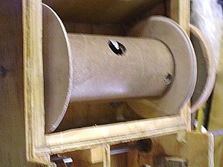
20-note Höffle build winds onto a 100 mm-diameter PVC tube with plywood end discs
(en_bouwhoeffle), so d starts near 100 mm and grows from there (which is exactly
the drift of §3). The paper length advanced per crank revolution — the millimetres
of tune consumed per turn of the hand — is v ÷ n_crank = π · d · R, and because no
source states either d precisely at any instant or the exact R, the
millimetres-of-paper-per-crank-revolution is an estimate (est.) and is never quoted
as a sourced number.
3.2.3 From paper speed to tempo: BPM = v ÷ s
The music is punched with musical events — the starts of notes, the pulse of the beat — spaced along the paper. Let s be the distance in millimetres between successive beats on the roll (the beat pitch; this geometry is owned by Encoding the Music, which sets how an arrangement is laid out along the paper). If beats are s mm apart and the paper moves at v mm/min, then beats pass the tracker bar at a rate of v ÷ s per minute — which is precisely tempo in beats per minute:
Tempo (BPM) = v ÷ s = (π · d · n) ÷ s
and substituting the ratio from §2.1:
Tempo (BPM) = (π · d · R · n_crank) ÷ s
This is the volume’s central equation. Read it plainly: for a fixed drum diameter d, drivetrain ratio R, and beat spacing s, tempo is directly proportional to crank RPM. Turn the handle twice as fast and the music plays twice as fast. There is no gearbox, governor, or clock between the hand and the tempo — the operator’s cadence is the tempo control. The relationship is exact; the caveat that spoils “fixed d” is §3.
Figure 3-1. The tempo chain. The hand crank turns at n_crank RPM (est. 40–70); a fixed drivetrain ratio R sets the take-up-spool speed n; the spool of effective diameter d advances the paper at v = π·d·n; and beats spaced s mm apart yield tempo = v ÷ s. For fixed d, R, and s, tempo is exactly proportional to crank RPM. The numbers d, R, s, and n_crank are illustrative and marked (est.); the relationship itself is exact.
3.2.4 A worked example (all inputs est.)
Take a set of illustrative-but-plausible numbers, every one marked (est.), and run
them through the exact relationship. Let the take-up drum sit at its bare Höffle size,
d = 100 mm (est.) (en_bouwhoeffle documents the 100 mm PVC drum; the value is
used here as an instantaneous estimate), and suppose the drivetrain delivers a take-up
speed of n = 12 RPM (est.) — consistent with, say, a crank at 60 RPM (est.) and a
reduction ratio R = 0.20 (est.).
Paper speed:
v = π · d · n = π × 100 mm × 12 rev/min ≈ 3770 mm/min ≈ 63 mm/s (est. inputs)
(π × 100 × 12 = 3769.9 mm/min; ÷ 60 = 62.8 mm/s.)
Now let the beats be punched s = 40 mm (est.) apart on the roll (a plausible beat pitch — the actual value is Encoding the Music’s to set). Tempo:
Tempo = v ÷ s = 3770 mm/min ÷ 40 mm ≈ 94 BPM (est. inputs)
(3769.9 ÷ 40 = 94.2 BPM; equivalently 62.8 mm/s ÷ 40 mm × 60 = 94.2 BPM.) About 94 beats per minute — a comfortable march/waltz tempo — from a crank turning once a second. Every input above is an estimate; the arithmetic that binds them is exact.
The proportionality is easiest to feel in a small table. Holding d = 100 mm (est.), R = 0.20 (est.), and s = 40 mm (est.) fixed, and sweeping the crank across its comfortable range:
Table 1 — comfortable range
| Crank RPM (est.) | Take-up n = R·n_crank (RPM) | Paper speed v = π·d·n (mm/min) | v (mm/s) | Tempo v÷s (BPM) |
|---|---|---|---|---|
| 40 | 8 | 2513 | 41.9 | 63 |
| 50 | 10 | 3142 | 52.4 | 79 |
| 60 | 12 | 3770 | 62.8 | 94 |
| 70 | 14 | 4398 | 73.3 | 110 |
Table 3-1. Tempo vs crank speed for fixed d = 100 mm (est.), R = 0.20 (est.), s = 40 mm (est.). Tempo tracks crank RPM one-for-one: a 75 % increase in crank speed (40 → 70 RPM) yields a 75 % increase in tempo (63 → 110 BPM). All inputs are illustrative estimates; the π·d·n ÷ s relation is exact.
The table makes the operator’s whole job visible: the entire musical tempo range of the instrument lives inside a 30-RPM band of hand speed. Thirty RPM is half a turn per second of difference between a stately 63 BPM and a brisk 110 BPM. The hand must resolve tempo to within a couple of RPM to hold a tune steady — which is exactly why §4 treats steady cranking as a skill.
3.3 The take-up-diameter tempo creep
Section 2 held d fixed. In reality it does not stay fixed, and this is the single most important complication in the whole tempo story.
3.3.1 Why the effective diameter grows
The take-up spool winds the played paper onto itself. As the roll plays, paper accumulates on the take-up drum, so the drum’s effective diameter grows steadily from its bare value toward a fully-wound value. Each wrap of paper adds twice the paper thickness to the diameter (one thickness on each side). With paper on the order of 0.1 mm thick (est.) and a bare drum of 100 mm (est.), each wrap adds about 0.2 mm (est.) to d.
The magnitude over a whole roll is an estimate, but it is easy to bound. The number of wraps is roughly the paper length divided by the average circumference (~300–380 mm). A short 5 m (est.) roll is about 14 wraps (est.), adding ≈ 3 mm (est.) to the diameter — call it ~3 %. A long 15 m (est.) roll is about 40 wraps (est.), adding ≈ 8 mm (est.) — call it ~8 %. Thicker card stock, or a generous roll, can push the accumulated build-up toward 10–20 mm, i.e. a ~10–20 % (est.) growth in effective diameter from start to finish. All of these figures are estimates; no hobby source measures the drift.
3.3.2 What the growth does to tempo — if the ratio is rigid
Now recall the exact relation of §2.3: tempo = π · d · R · n_crank ÷ s. If the crank-to-take-up ratio R were rigid — a positive gear or chain, with the take-up locked to the crank at a fixed tooth ratio — then d growing means tempo growing, for the same hand speed. The music would speed up through the roll even with a perfectly metronomic operator. A ~3–8 % diameter growth on a typical roll (est.) translates directly to a ~3–8 % tempo creep by the end of the tune (est.); a generous card roll could creep 10–20 % (est.). A tune starting at 94 BPM (est.) might finish near 100–104 BPM (est.) on a rigidly-geared take-up — audibly faster, and in the wrong direction (tunes rarely want to accelerate to the finish).
Figure 3-2. Take-up-diameter tempo creep, and why the clutch tames it. As played paper winds onto the take-up drum, the effective diameter grows from d0 (bare, ≈ 100 mm est.) toward a larger d (est. +3–20 % over a roll). Because v = π·d·n, a rigidly geared take-up would advance the paper — and the tempo — faster as the roll builds. A slipping friction clutch (inner-tube tyre plus clutch spring, jsart80; a spring-pressed pin coupling, en_20Hoffle2) lets the take-up over-run and slip, so the paper speed is set by drag and tension rather than by the growing diameter, largely suppressing the creep. Diameter and percentage figures are estimates.
3.3.3 Why real organs do not creep much: the slipping friction clutch
Real hobby builds do not gear the take-up rigidly, and this is the resolution of the paradox. The take-up is driven through a slipping friction clutch:
- Dennis Spinks describes an inner-tube tyre glued to the drive spool with a clutch spring that engages the drive and “gives great torque, far more than is needed” (jsart80, Dennis Spinks) — a friction coupling that transmits drive but slips when the take-up wants to run faster than the paper is actually being fed.
- The Höffle 20-note coupling is a positive/clutch hybrid: two interlocking pins,
one on the winding-reel shaft and one on the large transfer wheel, with a small
spring pressing the transfer wheel against the rear wall so a friction clutch is
always present (
en_20Hoffle2). The pins carry the drive; the sprung friction lets it slip for holding and rewind.
Because the coupling slips, the take-up spool is not forced to turn at exactly n = R·n_crank. Instead it turns as fast as it can pull paper, and it slips the remainder. The paper speed is then governed by the geometry of paper feed and tension rather than being dictated moment-to-moment by the growing drum diameter — the clutch absorbs the mismatch. This is the same clutch that lets a builder hold the paper, rewind, or clear a jam without shearing anything (Vol 02). The tempo creep of §3.2 is therefore largely suppressed in practice; the drift is a mechanism to understand, not a defect that ruins playback, precisely because the drive is friction-coupled rather than rigidly geared.
There is a corollary that ties the whole volume together. Since the take-up is free to slip and its diameter is drifting, the fixed gear number does not, by itself, pin the tempo. The one thing that reliably sets and holds the tempo is the operator’s steady cranking. The clutch removes the take-up drum from the tempo equation; the hand puts the tempo back in. That is why builders trim tempo by hand, and why the two documented “coarse” tempo adjustments are treated as setup, not performance, controls: Spinks notes that one can “build up the drive-spool tyre by adding 3 or 4 layers of inner tube, to speed up the drive” (jsart80) — increasing the driving-wheel diameter raises R, and Venable swaps a ~3:1 gear pair for rewind (jsart61). Both change R to move the whole tempo band up or down; neither is how one holds a beat during a tune. Holding the beat is the hand’s job.
3.4 The human factors: steady cranking is a skill
Here is the headline of the volume. Because the tempo is set by hand speed, and the crank turns only about once a second, holding a steady tempo is a genuine motor skill — and a documented chore. It is the first thing that separates a pleasant performance from a seasick one, and it is the reason two pieces of the machine exist largely to help the hand.
3.4.1 Why the hand drifts
Turning a crank at a constant rate sounds trivial and is not. The load on the crank is not constant: the feeder bellows present a lumpy, pulsating torque — hardest at the bottom of each compression stroke, near-free on the return — so the hand must push harder and softer several times per revolution just to keep the shaft turning evenly (the torque story is Vol 04’s; here it matters only as a disturbance to steady speed). Layered on top are the operator’s own fatigue, distraction, the natural human tendency to rush the exciting passages and drag the quiet ones, and the coarse feedback of a slow shaft. Hobby and busker-organ experience is blunt about the result: keeping a steady tempo is described as “a chore,” and operators “lose the ability to turn steadily very quickly” (busker-organ hobby consensus). A fresh cranker is steady for a minute; a tired one wanders.
Because tempo tracks crank RPM one-for-one (§2), every wobble in hand speed is a wobble in tempo. A crank that surges from 60 to 66 RPM on a loud phrase drags the tempo up ~10 % — from 94 to ~104 BPM (est.) — for as long as the surge lasts. There is no flywheel of “musical inertia” in the encoding to hide it; the paper simply speeds up with the hand. The tempo is as steady as the arm, and no steadier.
3.4.2 What helps: the flywheel and the reservoir
Two features of the machine exist, in part, to make the hand’s job easier. Both are developed fully in Vol 04 (torque and the flywheel) and Wind Systems (the reservoir); they are forward-referenced here because they are the practical answer to the steady-tempo problem.
- A flywheel — or a heavy driving / winding wheel — stores rotational energy on the easy part of each cycle and returns it on the hard part, smoothing the lumpy feeder torque so the crank coasts through the heavy strokes rather than being braked by them. A smoother torque is far easier to turn at a constant rate. No hobby source specifies a dedicated flywheel by mass or inertia — so any sizing is (est.) — but the heavy Formply / plywood winding wheel many builders already fit (jsart129, David Briggs) acts as a modest flywheel for free. The wheel that couples the hand to the drive doubles as the wheel that steadies the hand’s speed. Vol 04 develops this.
- The wind reservoir does the pneumatic half of the same smoothing. It stores wind between feeder strokes and delivers a steady pressure to the pipes, so a small wobble in crank speed does not translate into an audible wobble in pitch and volume. It cannot steady the tempo — the paper speed is mechanical, not pneumatic — but it hides the crank’s roughness from the sound of the pipes, which is why a reservoir-equipped organ tolerates an unsteady hand more gracefully. The reservoir belongs to Wind Systems; it is named here only as the sound-side counterpart to the flywheel’s speed-side smoothing.
Between them, the flywheel steadies the turning and the reservoir steadies the sound, and the operator learns to feel the pulse in the arm. But neither replaces the skill: on a hand-cranked organ the tempo is, finally, hand-made. That is at once the instrument’s charm and its difficulty — and it is exactly the quantity an electric-motor drive removes, for better and worse, in Vol 05 (a motor holds RPM perfectly, and with it a perfectly steady tempo, at the cost of the living hand).
3.4.3 A checklist of what sets and disturbs tempo
Table 2 — 4.3 A checklist of what sets and disturbs tempo
| Factor | Effect on tempo | Kind | Where owned |
|---|---|---|---|
| Crank RPM (the hand) | Sets it directly; tempo ∝ crank RPM | The control | This volume §2 |
| Beat spacing s on the roll | Fixed per arrangement; smaller s → faster tempo for same v | Encoded, fixed | Encoding the Music |
| Drivetrain ratio R | Fixed by wheel/gear sizes; sets the tempo band | Coarse setup | Vol 02; §3.3 |
| Building up the drive tyre | Raises R → shifts whole tempo band up (jsart80) | Coarse setup | §3.3 |
| Take-up drum diameter growth | Would creep tempo up if rigid; clutch suppresses it | Disturbance, tamed | §3 |
| Slipping friction clutch | Removes drum diameter from tempo; hand governs | Stabiliser | §3.3 |
| Lumpy feeder torque | Fights steady turning several times per rev | Disturbance | Vol 04 |
| Flywheel / heavy winding wheel | Smooths torque → steadier turning → steadier tempo | Stabiliser | Vol 04 |
| Reservoir | Steadies pitch/volume against crank wobble (not tempo) | Sound stabiliser | Wind Systems |
| Operator fatigue / rushing | Wanders the tempo; “a chore” to hold steady | Disturbance | §4.1 |
Table 3-2. What sets and disturbs the tempo. Only one factor — crank RPM — is the live control; the rest are either fixed at setup (R, s), suppressed disturbances (drum creep, tamed by the clutch), or stabilisers (flywheel, reservoir) that make the hand’s job easier without replacing it.

3.5 Summary
The tempo of a hand-cranked organ reduces to one exact relationship and a short list of caveats:
- The crank turns slowly — “RPM minimal” (jsart88), estimated at ~40–70 RPM (est.), about one revolution per second. Every downstream rate is small.
- Tempo is set by paper speed, and paper speed is exactly v = π · d · n, with take-up speed n = R · n_crank. Beats spaced s mm apart give Tempo (BPM) = π · d · n ÷ s = π · d · R · n_crank ÷ s. The relationship is exact; the worked example (d = 100 mm, n = 12 RPM → v ≈ 3770 mm/min ≈ 63 mm/s; s = 40 mm → ≈ 94 BPM) uses inputs that are all (est.).
- Tempo is proportional to crank RPM for fixed d, R, and s — the whole tempo range lives in a ~30-RPM band of hand speed (Table 3-1).
- The take-up drum’s diameter grows as paper winds on, which would creep the
tempo up ~3–20 % over a roll (est.) if the take-up were rigidly geared — but real
builds drive it through a slipping friction clutch (jsart80;
en_20Hoffle2) that removes the drum diameter from the tempo equation and largely suppresses the creep. - Therefore the operator’s steady cranking, not any fixed gear number, is the real tempo control — and holding it steady is a documented chore and a genuine skill. A flywheel / heavy winding wheel smooths the turning and the reservoir smooths the sound, but neither replaces the hand.
Vol 04 develops the torque and the flywheel that make steady cranking possible; Vol 05 shows how an electric-motor drive trades the hand’s living tempo for a motor’s perfect one. The beat spacing s that closes the tempo equation is Encoding the Music’s to set; the drivetrain ratio R that opens it is Vol 02’s.
Comments (0)