Turning The Crank · Volume 6
Turning the Crank — Vol 06: Speed Control & Automation
Volume 5 (“Electric-Motor Drive”) ended at a working conversion: a 12 VDC gearmotor coupled to the same grooved driving/winding wheel the hand crank uses, turning the drivetrain at the same tens of RPM the hand achieved so the bellows pump rate and the take-up/paper speed stay in their designed relationship (jsart110, Ronald Walters; jsart129, David Briggs). A motor spinning at a single fixed speed, however, is only half a drive. A hand does two things a bare motor does not: it varies the speed at will — pushing tempo, easing back, holding a phrase — and it reverses effort into the tedious business of rewinding the roll. This volume covers how a hobby build recovers both of those, and then follows the road past mere motor-assist to the fully self-playing machine.
The organising idea is a spectrum of autonomy. At one end the operator does everything by hand. One step in, a motor takes the muscle work but the operator still supervises. Further along, a motorised roll-player runs the whole cycle unattended. At the far end, MIDI dispenses with the paper and the crank altogether. Each step removes some effort — and gives up some of the living, hand-driven character that many builders value. That trade is stated here as a genuine trade, not a verdict.
Three threads run through the volume: PWM variable-speed control (how a duty cycle sets tempo), motorised rewind (the boring high-turn job the hand hates), and the automation spectrum with its authenticity-vs-convenience axis. The tempo mathematics itself — how paper speed and beat spacing set the musical BPM — lives in Vol 3 (“Speed, RPM & Tempo”); the motor-and-coupling hardware lives in Vol 5; the paper-roll and MIDI encoding medium belongs to the sibling dive “Encoding the Music.” This volume owns only the control and automation layer that sits on top of them.
6.1 PWM Variable-Speed Control
6.1.1 The principle: duty cycle → average voltage → average speed
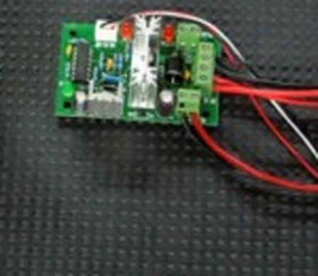
The documented conversion specifies a 12 VDC motor with variable speed control, both “readily available on eBay,” powered by a 12 V battery in a separate carrier (jsart110, Ronald Walters). The variable-speed control in that recipe is, in the overwhelming majority of low-cost eBay units, a pulse-width modulation (PWM) controller. Understanding what PWM does — and, just as important, what it does not do — is the core of this volume.
A PWM controller does not sit between the battery and the motor like a dimmer resistor, burning off the surplus as heat. Instead it switches the full 12 V supply on and off very rapidly — typically hundreds to tens of thousands of times per second — and varies the fraction of each switching cycle for which the supply is connected. That fraction is the duty cycle, expressed as a percentage:
duty cycle (%) = (on-time ÷ total cycle time) × 100
Because the switching is far faster than the motor’s mechanical response, the motor’s armature cannot follow the individual on/off pulses. Its inductance and rotational inertia average them out. What the motor “sees” is the average voltage across the switching cycle, and for an ideal switch that average is simply:
V(avg) = V(supply) × duty cycle
So at a 12 V supply, a 25 % duty cycle presents roughly 3 V average, a 50 % duty cycle roughly 6 V average, and a 100 % duty cycle the full 12 V. In a DC motor the no-load speed is very nearly proportional to the applied average voltage, so the average voltage sets the average speed, and therefore the tempo. Turning the controller’s knob from, say, 40 % up to 55 % raises the average voltage, raises the average driving-wheel RPM, and — because the crank → bellows and crank → take-up ratios are fixed by the mechanism (Vol 5) — raises the paper speed and the musical tempo together, exactly as a faster hand would (see Vol 3 for tempo = π·d·n ÷ s).
This is the whole appeal: smooth, continuous tempo control from a 12 V battery, with almost no power wasted as heat in the controller (the switch is either fully on, dropping near-zero volts, or fully off, carrying near-zero current). The sibling 31-note build takes the alternative route — a variable-voltage DC supply feeding a small motor to set its speed (en_31toets) — which reaches the same speed-vs-voltage result by adjusting the actual DC level rather than by chopping a fixed one. Both exploit the same underlying fact: DC motor speed tracks applied voltage. PWM simply synthesises the variable average voltage efficiently from a fixed battery.
6.1.2 What PWM does not do: it sets speed, not torque
A common and costly misreading is to treat the speed knob as a “power” or “strength” control. It is not. PWM sets the average voltage, and thereby the speed; it does not directly change the motor’s torque. Torque in a DC motor is set by armature current, which the load — the bellows/con-rod pumping load, the paper drag, and the drivetrain friction (Vol 4, “Torque, Effort & the Flywheel”) — draws as needed at whatever average voltage is present. Reducing the duty cycle lowers the speed the motor will settle at for a given load; it does not hand the motor extra pulling strength.
This distinction is not academic, because it drives the design of the whole motorised drive. If the drivetrain needs more torque to turn — a stiffer bellows, a tight new drive belt, cold grease — the answer is gearing (a larger reduction ratio in the gearmotor, which multiplies torque and divides speed; Vol 5), or a physically larger motor, not a change of duty cycle. The controller governs how fast; the gearmotor and its reduction govern how hard. Keeping those two ideas separate prevents the most common motorising disappointment: a builder winds the speed knob down expecting the motor to grind more powerfully through a stiff spot, and instead watches it stall.
6.1.3 The low-duty stall floor
Because low duty means low average voltage, and low average voltage means the motor develops only a weak turning effort at low speed, every PWM-driven drivetrain has a minimum usable duty cycle below which it simply stops. The drivetrain of a crank organ is not free-running: it must continuously overcome the pumping load of the feeders, the drag of paper past the tracker bar, and the stiction (static friction) in bearings, tyres and clutch. Static friction is higher than the friction of motion, so there is a threshold: below some duty the average voltage cannot break the drivetrain loose from rest, or cannot keep it crawling once loaded.
In practice this stall floor sits somewhere around a 20–30 % duty cycle for a typical small organ drive, though the exact figure depends on the motor, the gearing, the belt tension and how stiff the bellows are — treat any specific number as (est.) and find it on the bench for the actual build. The practical consequences:
- The controller’s usable tempo range is not 0–100 % but roughly the stall floor to 100 %. A well-matched gearmotor should reach the slowest wanted playing tempo at a duty comfortably above the stall floor, so there is margin before it dies. If the slowest musically useful tempo demands, say, a 15 % duty, the motor is geared too fast and will be twitchy and stall-prone at the bottom of its range; a larger reduction ratio moves the whole usable band upward into more stable territory.
- Starting from rest is the hardest moment (static friction is highest before anything moves). A drive that runs happily at 30 % once turning may need a brief nudge above that to break away. Some controllers ramp the duty up on start for this reason; on a simple knob controller the operator gives it a moment at higher duty and then eases back.
6.1.4 Choosing the PWM frequency: the whine-vs-torque trade
The second controller parameter — often fixed in cheap units, adjustable in better ones — is the PWM switching frequency, the rate at which the supply is chopped, in Hz. It trades two undesirables against each other.
- Too low a frequency (say a few hundred Hz up to a couple of kHz) puts the chopping rate squarely inside the audible band. The motor windings and laminations physically vibrate at the switching frequency (magnetostriction and winding forces), producing an audible whine or buzz at that pitch. On an organ, whose entire purpose is to make an agreeable sound, a motor singing a steady tone under the music is especially unwelcome.
- Too high a frequency (well up into tens of kHz) lifts the whine above hearing, but switching losses in the controller and, more importantly, the effect of the motor’s own inductance can slightly reduce the effective torque and efficiency at a given duty, and can stress a marginal controller. Very high frequencies also make low-duty operation harder because each on-pulse is so brief that the current barely rises before it is cut off.
The usable compromise for a small DC organ drive is a switching frequency high enough to move the whine out of the ear’s most sensitive range while keeping good low-speed torque — commonly in the region of a 16–25 kHz for units that advertise “silent” operation (values (est.) and controller-dependent). The practical test is simply to listen: if the motor sings, the frequency is too low; if it stalls or loses pull at moderate duty, the frequency (or the gearing) needs revisiting. Because the organ is a quiet-mechanism instrument, the acoustic requirement here is stricter than on, say, a power tool, and it is worth choosing a controller whose frequency is either high by default or adjustable.
6.2 On/Off and the Motorised Rewind
6.2.1 The motor as switchable assistance
The simplest use of the motor beyond a fixed run is the obvious one: an on/off switch in the battery line so the operator can start and stop the drive, and a speed knob to set the tempo while it runs. Even at this level the machine is only motor-assisted: a person still chooses when it plays, sets and rides the tempo, and stands with it. The muscle is gone; the supervision remains. This is the mode the documented conversion primarily describes — a Senior 20 that the motor turns while the operator attends to it (jsart110, Ronald Walters).
6.2.2 Powering the rewind — the boring, high-turn job
Where the motor earns its keep unarguably is rewinding the roll. Playing a roll unwinds it from the supply spool onto the take-up spool; before it can be played again it must be wound all the way back. By hand this is the drive’s least loved task: it is many turns, it is unmusical, and unlike playing it has no reward of sound to pace it — “the boring, high-turn job the hand hates.”
The motorised conversion explicitly captures this: the same 12 VDC motor that plays the roll can, reversed or re-clutched, drive the rewind (jsart110, Ronald Walters — his video series includes a “12 V Motor-Powered Music-Roll Rewind”). Rewind is mechanically the inverse of playback and, crucially, it is unloaded in the wind-raising sense — the bellows need not be pumped to wind paper back — so it can be run much faster than playing without straining anything. This is why the rewind gearing can be geared up: a gear pair “with a nice ratio of about 3:1” spins the take-up roughly three times faster for rewind, accepting the roughly threefold drop in torque because the rewind is unloaded (jsart61, Wallace Venable; see Vol 4 for the ratio math). Under PWM, the same controller that governs the gentle playing tempo can drive the rewind at high duty for a brisk return.
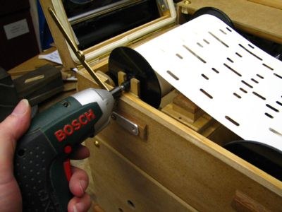
A parallel and very hobby-friendly solution uses no dedicated motor at all: a cordless screwdriver fitted with a 5 mm hex bit drives the hex hole in the standard Raffin spool directly (jsart84, Melvyn Wright). The screwdriver is the motor and speed control for the rewind — squeeze the trigger and the roll races back. The same article documents the hand alternative for completeness (a brass-rod handle with a 5 mm Allen key engaging the same hex), and a hinged bearing that drops out of the way so the power driver can reach the spool. The lesson is the general one of this volume in miniature: let the motor do the tedious, repetitive, high-revolution work, and reserve the hand for the part that wants judgement. Rewinding wants no judgement at all, so it is the first job to automate and the one almost every motorised build automates first.
6.3 The Automation Spectrum
The motor conversion is one point on a continuum that runs from a purely manual instrument to one with no human input during play at all. It is worth laying the whole continuum out, because each step is a distinct design with distinct hardware, and because the character trade (Section 4) shifts steadily as one moves along it.
6.3.1 Level 1 — hand-crank
The baseline. The operator turns the crank; that single motion both raises the wind (throws → con-rods → feeders) and advances the music (driving wheel → friction tyre/cord → take-up spool), as the whole dive’s thesis holds. Tempo is whatever the hand does moment to moment — which is at once the instrument’s expressive strength and, over a long play, its fatigue (Vol 3 notes that holding a steady tempo by hand is a genuine, tiring skill; “cranking to keep steady tempo is a chore”). No electronics, no battery, no failure modes beyond the mechanical. Full presence, full effort.
6.3.2 Level 2 — motor-assisted crank
A 12 VDC gearmotor coupled to the driving/winding wheel replaces the muscle, and a PWM controller replaces the hand’s tempo-setting (jsart110, Ronald Walters; coupling via the motor-drive wheel groove and 8 mm motor coupling, jsart129, David Briggs). The operator still supervises — switches it on, sets and can ride the tempo knob, changes and rewinds rolls, and stands with the instrument — but no longer supplies the physical work. This is the step the documented hobby conversion occupies. It removes the effort and, if the controller is held at a fixed duty, removes the involuntary tempo wobble too. It does not, by itself, make the machine self-playing: someone is still there.
6.3.3 Level 3 — fully automatic roll-player
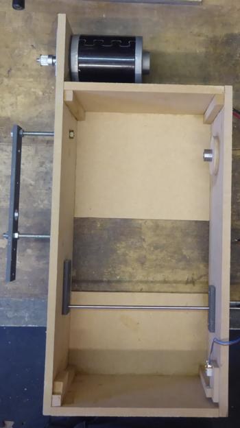
Here the human leaves the loop during play. The work-in-progress automatic roll-player is a self-contained motorised roll box: a motor mounted at the top, 4 mm and 8 mm shafts, and a solenoid, with the roll-box body sized 190 × 127 mm for the 31-note scale and 160 × 127 mm for the 20-note scale (jsart138, Melvyn Wright). The motor advances (and rewinds) the roll; the solenoid performs the switching the operator’s attention used to — for example handling the end-of-roll/rewind sequencing — so the box can run a roll through and reset without a hand on it. This is a true self-player: load a roll, start it, and it plays and resets itself. The organ still makes its sound pneumatically from the same paper; what has been automated is the operation, not the sound generation.
6.3.4 Level 4 — MIDI
At the far end the paper roll and the crank both disappear. The 31-note build documents going MIDI-driven instead of paper-roll (en_31toets): the note data lives as MIDI, electric valves (solenoids) open the pipes directly, and a small motor and controller need only supply wind. There is no roll to advance and no crank to turn for the music — the timing comes from the MIDI stream. This is the most autonomous and the most flexible (any tune the file library holds, instant “rewind,” no physical roll to cut, store or wear) and it is also the furthest from the hand-cranked original. The MIDI/encoding medium itself — file formats, the note map, how a roll is transcribed to MIDI — belongs to the sibling dive “Encoding the Music”, cross-referenced here; this volume notes only that MIDI is the terminal point of the automation spectrum, where operation, roll transport and crank are all gone at once.
6.3.5 The spectrum as a table
Table 1 — 3.5 The spectrum as a table
| Level | What it is | Effort removed | Authenticity cost | Source |
|---|---|---|---|---|
| 1 — Hand-crank | Operator turns the crank; one motion raises wind and advances music | None — all effort is manual | None; full hand presence and rubato | Baseline (whole dive) |
| 2 — Motor-assisted crank | 12 VDC gearmotor + PWM control drives the wheel; operator supervises and sets tempo | Muscle effort; involuntary tempo wobble (at fixed duty) | Loses the hand-driven micro-tempo, but a person is still present | jsart110, Ronald Walters (coupling: jsart129, David Briggs) |
| 3 — Automatic roll-player | Self-contained motorised roll box: motor + solenoid; plays and resets a roll unattended | Muscle and supervision during play | Loses the operator’s live presence; still real pipes and paper | jsart138, Melvyn Wright |
| 4 — MIDI | No paper, no crank; MIDI data drives the valves; motor only supplies wind | Muscle, supervision and the physical roll/crank | Furthest from the hand-cranked original; maximal flexibility | en_31toets (medium: “Encoding the Music”) |
6.4 The Authenticity-vs-Convenience Trade
Every step to the right on the spectrum removes work — and removes something else. It is worth naming both halves plainly, because the choice is real and personal, and stating it as a verdict would be false to the hobby.
6.4.1 What motorising gives
Motorising removes the physical effort. A long busking session or a fete’s worth of playing is genuinely tiring by hand; the drivetrain must be turned continuously against a lumpy, pulsating bellows load (Vol 4). A gearmotor does this without fatigue and without the arm’s slow drift off tempo. Held at a fixed duty, a PWM drive delivers a rock-steady tempo that no hand can match over many minutes — the involuntary “tempo wobble” that Vol 3 identifies as the central difficulty of hand-cranking simply disappears. And at the far end, automation enables self-play: an auto roll-player or a MIDI system can perform unattended, which is exactly what a shop-window display, an exhibit, or a builder who wants to hear the machine while doing something else may want. These are not small conveniences; for some uses they are the difference between an instrument that gets played and one that does not.
6.4.2 What motorising takes
The same steadiness is also a loss. A hand-cranked organ has living, hand-driven rubato — the tiny, mostly unconscious pushes and eases of tempo that a player puts into a phrase, the slight lean into a strong beat, the breath before a repeat. A motor at fixed duty plays metronomically; it cannot lean or breathe. More broadly, the busker organ is partly a performance of presence: the turning hand, the visible effort, the direct human connection between the operator and the crowd. A machine playing itself in a box is a different, more distant thing — impressive in its own way, but not the same social object. Many builders prize precisely the effort and the imperfection that motorising removes; for them the “chore” of steady cranking is not a defect to engineer away but the very substance of the instrument.
6.4.3 The trade cuts both ways
The forum commonplace that “cranking to keep steady tempo is a chore” is true — and it cuts both ways. To the builder who wants an effortless, reliable, self-playing display, the chore is a problem and motorising is the solution. To the builder who wants the hand-cranked instrument to be a hand-cranked instrument, the chore is the point, and the wobble is character. Most builders end up somewhere pragmatic in the middle — many keep the hand crank fully usable and add the motor as an option, precisely the arrangement the built-up drive supports when it cuts the winding wheel’s groove “for a motor drive” and fits the handle with an 8 mm motor coupling, so the same wheel takes either the hand or a belt (jsart129, David Briggs; Vol 5). That dual-use design is the diplomatic answer to the whole trade: build the drive so the operator can choose, roll by roll, which end of the spectrum to play from. Nothing in this volume argues for one end over the other — only that the choice is real, that each end costs what the other buys, and that a well-made drive need not commit to either irreversibly.
6.5 Summary
- A PWM controller switches the 12 V supply on and off rapidly; the duty cycle sets the average voltage, which sets the average motor speed and hence the tempo — smooth, efficient tempo control from a battery (jsart110, Ronald Walters). The sibling variable-voltage approach reaches the same result by adjusting the DC level directly (en_31toets).
- PWM sets speed, not torque. Torque comes from gearing and motor size; the duty knob governs how fast the drive turns, not how hard it pulls. Below a roughly 20–30 % duty (est.) the average voltage cannot overcome drivetrain stiction and the motor stalls — so a well-matched gearmotor reaches the slowest wanted tempo above that floor. Choose a switching frequency high enough (≈16–25 kHz, est.) to keep the whine out of the ear while retaining low-speed torque.
- Let the motor do the tedious rewind — the boring, high-turn, unloaded job: a reversed/geared-up drive (≈3:1, jsart61, Wallace Venable) or simply a cordless screwdriver with a 5 mm hex bit into the Raffin spool’s hex hole (jsart84, Melvyn Wright).
- The automation spectrum runs hand-crank → motor-assisted crank (jsart110) → automatic roll-player (motor + solenoid roll box, 190 × 127 mm for 31-note / 160 × 127 mm for 20-note; jsart138, Melvyn Wright) → MIDI (no paper, no crank; en_31toets — see “Encoding the Music”).
- The authenticity-vs-convenience trade is genuine and personal: motorising removes effort, tempo wobble and the need for a person, and enables self-play, but also removes the living rubato and the busker’s presence many builders value. A dual-use drive (hand or motor through one wheel; jsart129) lets the operator choose which end to play from — the choice, not a verdict.
Cross-references: Vol 3 (“Speed, RPM & Tempo”) for tempo = π·d·n ÷ s and the steady-cranking skill; Vol 4 (“Torque, Effort & the Flywheel”) for the torque / gearing / lumpy-load mechanics; Vol 5 (“Electric-Motor Drive”) for the gearmotor, coupling and speed-matching hardware; and the sibling dive “Encoding the Music” for the paper-roll and MIDI medium at the far end of the spectrum.
Comments (0)