Turning The Crank · Volume 4
Turning the Crank — Vol 04: Torque, Effort & the Flywheel
Vol 03 followed the one quantity the operator controls with a bare hand — how fast the crank turns — and showed that musical tempo is proportional to crank speed. It closed on a promise: that holding a steady tempo is a skill made possible by two features of the machine that smooth the operator’s work. This volume develops the physics behind that work. It asks the complementary question to Vol 03’s “how fast?”: how hard? Why is one organ a pleasure to crank and another a fight; where does the effort come from; how does the handle length, or a gear ratio, change the force the hand feels; and how do a heavy wheel and the wind reservoir turn a lumpy, pulsating load into something a human arm can turn evenly.
The volume rests on two textbook relations, both recomputed here and checked against the two sourced gear cases in the hobby corpus. The first is torque equals force times radius (τ = F·r) — the handle length is a lever, and a longer handle trades hand force for reach (§1). The second is the gear/pulley ratio law — speed and torque trade inversely through any reduction, and neither trade creates power (§2). With those in hand, §3 catalogues what makes an organ hard to crank — the pulsating feeder load above all — and §4 explains how a flywheel, or the heavy winding wheel that already exists on most builds, stores and returns rotational energy to smooth that lumpiness, with the wind reservoir doing the identical job on the pneumatic side.
Voice / units / sourcing note. Torque is given in newton-metres (N·m), force in newtons (N), lengths in millimetres (mm) with metres shown where a calculation needs SI, and efficiencies and ratios as pure numbers or per-cent. The relations τ = F·r, ω_out = ω_in·(T_driver ÷ T_driven), and τ_out = τ_in·(T_driven ÷ T_driver)·η are derived and stated exactly. Every illustrative input — a handle length, a hand force, a feeder area — is marked (est.), because no hobby source states these numbers; the arithmetic that binds them is exact. Crucially, no hobby source specifies a flywheel by mass or moment of inertia. The flywheel here is a principle — documented rotational mechanics — and any sizing is flagged (est.). Wind pressures and feeder areas belong to Wind Systems and are used here only as illustrative inputs to a cranking-effort estimate, pointed back there, not re-derived.
4.1 Torque = force × radius
The effort the operator feels at the handle is not a force, it is a torque — a turning effort — and the distinction is the whole of §1. A force pushes in a straight line; a torque twists about an axis. The crankshaft is turned by the hand pushing on a handle offset from the shaft axis, and the twisting effort delivered to the shaft depends on both how hard the hand pushes and how far out the handle sits.
4.1.1 The relation and the moment arm
The relation is the definition of torque for a force applied at right angles to a lever arm:
τ = F · r
where τ is the torque about the shaft axis (N·m), F is the tangential force the hand applies at the handle grip (N), and r is the moment arm — the perpendicular distance from the shaft axis to the line of the applied force, i.e. the length of the crank handle (m). “Tangential” matters: only the component of the hand’s push acting perpendicular to the handle arm does useful turning work; a push directed along the arm produces no torque. In practice the operator’s hand applies force roughly tangentially, and the worked figures below assume the ideal tangential case.
The handle, in other words, is a lever, and r is its lever arm — the single most important lever in the machine from the operator’s point of view, because it sets the mechanical advantage between the hand and the crankshaft: for a given torque demanded by the organ, a longer handle lets the hand supply it with less force.
4.1.2 The worked example: a longer handle needs less force
Take an illustrative crank torque and see what two handle lengths demand of the hand. Suppose the crankshaft, at some instant, needs τ = 1.2 N·m to keep turning against the feeders and friction (a plausible order of magnitude; see §3, and marked (est.) as an input). With a handle of moment arm r = 60 mm = 0.060 m (est.), the tangential hand force required is:
F = τ ÷ r = 1.2 N·m ÷ 0.060 m = 20 N (est. inputs)
Twenty newtons is about the weight of a 2 kg bag of sugar held against gravity — easily sustained, but felt, and felt several times per revolution as the load pulses (§3). Now lengthen the handle to r = 90 mm = 0.090 m (est.) — a 50 % longer arm — and demand the same 1.2 N·m from the shaft:
F = τ ÷ r = 1.2 N·m ÷ 0.090 m = 13.3 N (est. inputs)
(1.2 ÷ 0.090 = 13.33 N.) The same shaft torque now costs the hand only 13.3 N instead of 20 N — a one-third reduction in force for a 50 % longer handle. The arithmetic is inverse-proportional and exact: force scales as 1 ÷ r for fixed torque, so multiplying the handle length by 1.5 divides the force by 1.5 (20 ÷ 1.5 = 13.3). The torque the organ actually sees at the crankshaft is unchanged — the organ neither knows nor cares how long the handle is; it only feels 1.2 N·m either way. What changes is the deal the hand gets to deliver that 1.2 N·m.
Figure 4-1. The crank handle as a lever. Both handles deliver the identical shaft torque of 1.2 N·m, but the longer 90 mm arm (right) demands only 13.3 N of hand force against the 20 N the 60 mm arm (left) requires — because for a fixed torque, force scales as 1 ÷ r. The handle length is the mechanical advantage between the hand and the crankshaft. Torque and lengths are illustrative (est.); τ = F·r is exact.
4.1.3 Why handles are not made arbitrarily long
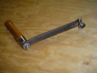
If a longer handle always lightens the hand, why not fit a very long one? Three limits bound it, and they explain the modest handle lengths on real builds. First, geometry and portability: the handle sweeps a circle of diameter 2·r that must clear the case, the operator’s body, and the transport footprint — busker organs are carried and their cranks often removable for exactly this reason (jsart57, Wallace Venable, whose crank arm is 1/8″ × 3/4″ steel, hitch-pin retained so it lifts off). Second, stroke and cadence: the hand travels farther per revolution on a longer handle (2π·r), so at the same RPM it moves faster and through a larger arc — comfortable only up to a point. Third, and most subtly, a longer handle lowers the force but does nothing to the power the operator must supply (§2.4): the reduced force is paid back exactly as increased hand travel, so a long handle makes a heavy organ feel lighter to pulse against but does not reduce the total work of playing a tune. Handle length is chosen to put the peak force in a comfortable band while keeping the swept circle sane.
4.2 The gear and pulley ratio math
The handle is one lever; the drivetrain is a chain of others. Vol 02 traced the mechanical path — driving wheel, friction tyre or drive cord, idler, take-up spool — and Vol 03 used the speed half of the gear law to get from crank RPM to tempo. This section states both halves exactly, speed and torque together, because torque is what this volume is about, and then checks the law against the two gear ratios that the hobby corpus actually documents.
4.2.1 The two exact relations
For any pair of meshing gears, or any belt/friction pair treated by their pitch (or effective) diameters, with a driver (the input member) and a driven (the output member), the output speed is:
ω_out = ω_in × (T_driver ÷ T_driven)
where ω is angular speed (rev/min or rad/s — the ratio is dimensionless so either works) and T is tooth count (or, equivalently, pitch diameter for gears, or effective wheel diameter for a friction/belt drive). Read it plainly: if the driven member has more teeth than the driver, the ratio T_driver ÷ T_driven is less than 1 and the output turns slower than the input — a reduction. If it has fewer, the output turns faster.
Torque runs the opposite way, and picks up an efficiency factor:
τ_out = τ_in × (T_driven ÷ T_driver) × η
where τ is torque (N·m) and η is the mechanical efficiency of the mesh (0 < η ≤ 1; a good gear or belt pair is η ≈ 0.9–0.98, i.e. 90–98 %). The tooth ratio is inverted relative to the speed relation. The consequence is the single most useful fact about any gear train: speed down ⇒ torque up, and speed up ⇒ torque down. A reduction that halves the speed roughly doubles the torque (less the efficiency loss); a step-up that triples the speed cuts the torque to about a third. The efficiency η only ever removes a little torque — it never adds — so the real torque multiplication is always slightly less than the ideal tooth ratio promises.
4.2.2 Check against jsart88 — the 1:1 right-angle drive
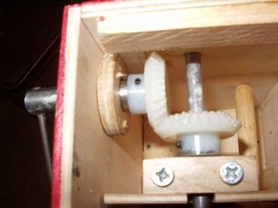
Dwayne Glanton relocates a Busker’s hand crank to the side of the case using two moulded-nylon miter gears (McMaster-Carr #7297K16: 20° pressure angle, 24 diametral pitch, 30 teeth, 1.25″ (≈ 31.75 mm) pitch diameter, 1/4″ (≈ 6.35 mm) bore) meshing at a right angle (jsart88, Dwayne Glanton). Both gears carry 30 teeth, so the ratio is:
ω_out = ω_in × (30 ÷ 30) = ω_in × 1.00 — no speed change τ_out = τ_in × (30 ÷ 30) × η = τ_in × η ≈ τ_in — no torque change (bar the small η loss)
This is a pure right-angle direction change: the crank turns the crankshaft at the same speed and (very nearly) the same torque it would with the handle mounted directly, merely redirecting the axis by 90° so the handle sits on the side. It is not a reduction and has no tempo or effort effect beyond the small friction of the extra mesh — which is why Glanton could choose it freely for ergonomic convenience. His remark that “since the RPM of the crankshaft is minimal, steel should make a good bearing” (jsart88) is the same slow-shaft fact Vol 03 leaned on: at tens of RPM (est. 40–70), even the efficiency loss of a nylon miter pair is trivial in absolute terms.
4.2.3 Check against jsart61 — the ~3:1 rewind step-up
Wallace Venable’s rewind mechanism uses a gear pair “with a nice ratio of about 3:1” to spin the take-up spool roughly three times faster than the handle for the rewind stroke (jsart61, Wallace Venable). Here the drive is a step-up (the take-up is the output and turns faster), so T_driver ÷ T_driven ≈ 3:
ω_out = ω_in × 3 = 3 × ω_in — the take-up spins ~3× the handle τ_out = τ_in × (1 ÷ 3) × η ≈ τ_in ÷ 3 — the torque at the take-up is ~1/3
The take-up turns three times faster and delivers about one-third the torque. That penalty is acceptable precisely because rewind is unloaded: the feeders are not pumping, the tracker bar is not being read, and the only load is slack paper and bearing friction — a tiny fraction of the playing torque. Trading two-thirds of the torque for triple speed is a good bargain when there is almost nothing to pull against. The same trade would be poor on the playing drive, where the feeders demand real torque; there builders keep the take-up geared down, not up (Vol 03 §2.1: a playing drive typically has R well below 1, the take-up turning slower than the hand).
4.2.4 A gear ratio does not change power
One guardrail must be stated flatly, because it is the commonest error in reasoning about gearing: a gear or belt ratio does not create power. Power is the product of torque and angular speed, P = τ·ω. Push the two relations of §2.1 through that product:
P_out = τ_out · ω_out = [τ_in · (T_driven ÷ T_driver) · η] · [ω_in · (T_driver ÷ T_driven)] = τ_in · ω_in · η = P_in × η
The tooth ratios cancel exactly, leaving only the efficiency η. Output power equals input power times efficiency — always slightly less than the input, never more. A reduction buys torque by spending speed; a step-up buys speed by spending torque; neither manufactures the product of the two. This is conservation of energy, and it is why the handle-length trade of §1.2 lightens the force but not the work, and why no arrangement of wheels makes a genuinely hard organ free. The only things that reduce the power the operator must supply are reducing the load (lower wind pressure, less friction, §3) or accepting a slower tempo. Gearing redistributes effort between force and speed; the flywheel of §4 redistributes it in time. Neither is a free lunch.
The two ratio cases, and the general trade, gather into one table:
Table 1 — The two ratio cases, and the general trade, gather into one table
| Case | Ratio T_driver ÷ T_driven | Output speed ω_out | Output torque τ_out | Power | Source / use |
|---|---|---|---|---|---|
| Right-angle miter | 30 ÷ 30 = 1.00 | = ω_in (no change) | ≈ τ_in (× η) | = P_in × η | jsart88 (Glanton) — relocate crank, no reduction |
| Rewind step-up | ≈ 3 | ≈ 3 × ω_in (faster) | ≈ τ_in ÷ 3 (weaker) | = P_in × η | jsart61 (Venable) — fast unloaded rewind |
| Playing reduction (typ.) | < 1 (e.g. 0.2) | < ω_in (slower take-up) | > τ_in (stronger) | = P_in × η | Vol 03 §2.1 — take-up slower than hand |
| General law | k | ω_in × k | τ_in × (1 ÷ k) × η | P_in × η | ω down ⇒ τ up; power never rises |
Table 4-1. The gear/pulley ratio law and the two sourced hobby cases. Speed and torque trade inversely through the tooth (or diameter) ratio k; power is conserved to within the efficiency η ≤ 1. The 1:1 miter pair (jsart88) changes neither; the ~3:1 rewind step-up (jsart61) triples speed and thirds torque, tolerable only because rewind is unloaded. No case adds power.
4.3 What makes an organ hard to crank
With the two lever laws in hand, the practical question is where the torque demand at the crankshaft actually comes from. An organ that is hard to crank is hard because the crankshaft is fighting a real, and largely pulsating, load. There are three contributions, in rough order of how much they dominate the feel of the handle: the feeder/con-rod pumping load, ordinary friction and stiction, and paper drag. The first is the interesting one, because it is not steady — it is inherently lumpy, and that lumpiness is the entire reason §4’s flywheel exists.
4.3.1 The pulsating feeder load — an inherently lumpy torque
The dominant load on the crankshaft of a playing organ is the work of raising the wind. Vol 02 traced the linkage: throws on the crankshaft drive connecting rods that reciprocate the feeder bellows — two feeders on a Basic 20, three on a 120° three-lobed crankshaft for the Universal/Senior (Wind Systems owns the bellows and reservoir; this dive owns only the crank → con-rod → feeder linkage). The key fact for torque is that a feeder’s resistance is not constant through its stroke.
On the compression stroke the con-rod squeezes air out of the feeder into the reservoir against the reservoir pressure, and resistance is greatest near the bottom of the compression stroke, where the feeder does the most work against the highest instantaneous back-pressure and the crank-throw geometry is least favourable. On the return (intake) stroke the feeder draws fresh air past a light flap valve at almost no pressure — the con-rod is nearly free. So each feeder, once per revolution, presents a load that climbs to a hard peak then falls to nearly nothing: a lump of torque, not a level one. A single-feeder organ would surge hard once per revolution and coast the rest — brutally uneven.
This is why the multi-feeder crankshaft is staggered. With three feeders whose throws are 120° apart, the three lumps are spread evenly around the revolution — as one feeder passes the hard bottom of its stroke another is in its easy return (Wind Systems; consistent across the sibling builds). Staggering does not remove the lumpiness — each feeder is still hard-then-easy — but it overlaps three lumps out of phase, so their sum is far flatter than any one alone. The residual ripple in the total crankshaft torque is what the flywheel of §4 finally smooths. Two feeders at 180° (Basic 20) flatten it less well than three at 120°; more feeders, better staggered, give a smoother crank at the cost of more mechanism.
An illustrative sense of the magnitude — every input (est.), the real values owned by Wind Systems — anchors why the peak matters. The reservoir runs at about 5 in H₂O ≈ 1.245 kPa (Wind Systems; context only). Suppose a feeder presents an effective plate area of 150 mm × 100 mm = 0.015 m² (est.). The pneumatic force resisting the feeder near full compression is then of order:
F_feeder ≈ p · A = 1245 Pa × 0.015 m² ≈ 18.7 N (est. inputs)
Acting through a crank throw (the con-rod’s effective moment arm on the shaft) of about 12 mm = 0.012 m (est.), that one feeder’s peak torque contribution near bottom-of-stroke is roughly:
τ_feeder,peak ≈ F_feeder · r_throw ≈ 18.7 N × 0.012 m ≈ 0.22 N·m (est. inputs)
falling to near zero on the return. Three such feeders staggered at 120° never peak together; the crankshaft sees a rippling sum whose peaks still poke through, and the 1.2 N·m of §1 is the same order of magnitude once friction and the other feeders are added — which is why 20 N at a 60 mm handle is a realistic peak hand force. The numbers are estimates; the shape is not: the feeder load is a train of lumps, hardest at the bottom of each compression stroke and near-free on each return.
4.3.2 Reservoir pressure and pipe demand set the height of the lumps
The height of each feeder lump scales with two things the operator can feel change from tune to tune. The first is reservoir pressure × feeder area: a higher wind pressure (a stiffer spill-valve spring, a louder-voiced organ) multiplies the force on every feeder plate directly (F = p·A), so a higher-pressure organ is straightforwardly harder to crank. The second is how much air the pipes are drawing: a big chord with many pipes speaking, or larger pipes with bigger toe holes, empties the reservoir faster, so the feeders must do more net work per revolution to keep it full — the crank gets heavier on the loud passages and lighter on the sparse ones. Bigger pipes and higher pressure both mean more air moved per revolution against more back-pressure = more torque at the crank. This is a genuine cross-coupling between the music and the effort: a densely-orchestrated fortissimo is literally harder to crank than a thin passage, which is one more disturbance the operator’s arm must ride over (Vol 03 §4). The wind physics — pressures, valve behaviour, reservoir sizing — is Wind Systems’ to develop; here it enters only as the thing that sets how tall the torque lumps are.
4.3.3 Friction, stiction, and paper drag — the steady baseline
Underneath the pulsating feeder load sits a more or less steady resistance from friction, and it matters most at one moment: starting from rest. Static friction (stiction) in the crankshaft bearings, the con-rod journals, the driving-wheel and idler bearings, and the friction tyre’s rolling contact is higher than the kinetic friction once things are moving, so the crank is always hardest to start and eases once it is turning — the familiar “get it over the first bump” feel. Hobby practice attacks this friction directly: con-rod journals are lubricated with talcum powder, “a natural slip surface on wood, Teflon-like,” or better with graphite (jshints, Charles Darley / Melvyn Wright); bearings are chosen generously (pillow blocks on 8 mm steel, jsart129, David Briggs; brass bushes, jsart57, Venable); and the slow shaft speed (Vol 03) means even crude bearings run cool and easy. The friction tyre in the music drive adds its own small, steady drag, and it is a wanted drag — Dennis Spinks notes his inner-tube-tyre clutch “gives great torque, far more than is needed” (jsart80, Dennis Spinks), i.e. there is grip to spare, so the tyre is never the limiting effort. Finally the paper drag — the tension needed to pull the roll off its supply spool and past the tracker bar — is small and steady, a minor addition to the baseline. None of these three is lumpy; together they set the floor under the feeder ripple, and their stiction sets the starting effort.
The factors, and what each does to the effort, gather into a checklist:
Table 2 — The factors, and what each does to the effort, gather into a checklist
| Factor raising cranking effort | Steady or pulsating? | What it scales with | Where owned |
|---|---|---|---|
| Feeder compression (per feeder) | Pulsating — hard at bottom of stroke, free on return | Reservoir pressure × feeder area × throw | §3.1; Wind Systems (pressure/area) |
| Number & phasing of feeders | Sets how the lumps overlap | 3 at 120° flatter than 2 at 180° | §3.1; Wind Systems |
| Reservoir pressure | Raises every lump’s height | Spill-valve spring; voicing | §3.2; Wind Systems |
| Pipe air demand (orchestration) | Pulsating with the music | Number & size of speaking pipes | §3.2; Wind Systems / Pipes |
| Bearing & journal friction | Steady (stiction higher at start) | Lubrication, bearing quality | §3.3; jshints, jsart129/57 |
| Friction-tyre / clutch drag | Steady, wanted (grip to spare) | Tyre grip, clutch spring | §3.3; jsart80 |
| Paper drag | Steady, small | Roll tension, supply-spool friction | §3.3; Vol 02 |
| Starting from rest | One-time stiction bump | Static vs kinetic friction | §3.3 |
Table 4-2. What makes an organ hard to crank. The dominant and the interesting contribution is the pulsating feeder load (§3.1) — inherently lumpy, hardest at the bottom of each compression stroke — whose height is set by wind pressure and pipe demand (§3.2). Friction, tyre drag, and paper drag form a steady baseline whose stiction is felt most at start-up (§3.3). Wind pressures and areas are Wind Systems’ to quantify.
4.4 The flywheel: smoothing the lumpy torque
Section 3 established the problem: the crankshaft torque demand is a train of lumps, hardest at the bottom of each feeder’s compression stroke and near-free on the return, sitting on a steady friction floor. A human arm can supply a smooth, roughly constant turning effort far more easily than one that surges several times per revolution — and if the arm cannot instantly match the surges, the crank slows on each hard lump and speeds on each easy gap, which (Vol 03 §2) is directly a tempo wobble. The machine’s answer is to put a flywheel in the rotating system.
4.4.1 The principle: store on the easy part, return on the hard part
A flywheel is simply a rotating mass with significant moment of inertia — a heavy wheel — rigidly coupled to the shaft. Its usefulness follows from one fact: a spinning mass stores kinetic energy, E = ½·I·ω², where I is its moment of inertia (kg·m²) and ω its angular speed. Because that stored energy is large compared with the little pulses the feeders demand and release each fraction of a revolution, the flywheel acts as a rotational energy buffer:
- On the easy part of each cycle — a feeder’s free return stroke, the gaps between the staggered lumps — the operator’s hand is supplying more torque than the shaft momentarily needs, so the surplus energy goes into speeding the flywheel up by a tiny, imperceptible amount: the flywheel stores energy.
- On the hard part — the bottom of a compression stroke — the shaft needs more torque than the hand is delivering at that instant, so the flywheel gives back the energy it just banked, slowing down by a tiny amount to do so: the flywheel returns energy, coasting the crank through the heavy stroke.
The result is that the crankshaft speed barely varies through the cycle even though the torque demand varies a great deal, and the force the hand must supply is smoothed toward the average torque instead of chasing every peak. The flywheel does not reduce the average effort (that would violate §2.4 — it stores and returns, it does not create), and over a full cycle it neither gains nor loses net energy. What it does is spread the lumps out in time, converting a pulsating load the hand would find jerky and tempo-destroying into a nearly steady one. The heavier the wheel (larger I) and the faster it turns, the more energy it buffers and the smoother the result — until the extra mass makes the organ harder to start and to carry.
Figure 4-2. The lumpy feeder torque and how a flywheel evens it out. Over one crank revolution, three feeders staggered at 120° each present a torque hump — hard at the bottom of the compression stroke, near-free on the return — so the raw demand (solid) rises and falls three times per turn. A flywheel absorbs the shaded surplus above the mean at each peak and returns it in each trough, so the crank turns at nearly the constant mean torque (dashed) rather than surging. The wind reservoir performs the identical smoothing on the pneumatic side, storing wind between strokes for steady pressure. Curve shape is schematic; no source specifies the flywheel inertia (est.).
4.4.2 The reservoir does the pneumatic half of the same job
The flywheel smooths the mechanical side — the speed of the crank and the force at the hand. The organ has a second smoother doing the same thing on the pneumatic side: the wind reservoir. The feeders deliver wind in gusts — full during compression, nothing during return — yet the pipes need steady pressure for steady pitch and volume. The reservoir, a sprung bellows storing pressurised air between the feeders and the pipes, stores wind on each delivery stroke and gives it back during the gaps, so the pipes see nearly constant pressure though the feeders pump in pulses. It is the pneumatic analogue of the flywheel — storing and returning energy, one as rotational kinetic energy in a spinning mass, the other as pressure-volume energy in a sprung air store — to convert a pulsating supply into a steady output.
The two smoothers cover the two symptoms of the same lumpy load. The flywheel keeps the crank speed steady, which (Vol 03) keeps the tempo steady; the reservoir keeps the wind pressure steady, which keeps pitch and volume steady. A generous reservoir tolerates an unsteady hand gracefully — the sound stays smooth even when the turning is rough — but it cannot fix the tempo, because paper speed is mechanical, not pneumatic. That is the flywheel’s department. The reservoir belongs to Wind Systems, which owns its sizing, spill valve, and pressure regulation; it is named here only as the sound-side counterpart to the flywheel’s speed-side smoothing — the same idea applied to the two halves of the crank’s job (Vol 01’s thesis: one rotation, two jobs).
4.4.3 The heavy winding wheel is already a modest flywheel
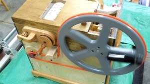
No hobby build in the corpus fits a dedicated flywheel, and no source specifies a flywheel by mass or moment of inertia — so any inertia figure would be an estimate (est.) and none is offered. But the principle is quietly present anyway, because the driving/winding wheel is heavy enough to serve as a modest flywheel for free. David Briggs makes his winding handle and wheel from 17 mm Formply — a dense plywood — and cuts a groove in the wheel “for a motor drive,” fitting the handle “using an 8 mm motor coupling” (jsart129, David Briggs). A wheel of that material and size, rigidly coupled to the crankshaft, carries real rotational inertia at the shaft’s tens of RPM, and does exactly the storing-and-returning of §4.1: it smooths the feeder ripple and steadies the hand, whether or not the builder calls it a flywheel. Wallace Venable’s solid wood drive wheel (jsart57, Wallace Venable) does the same. The flywheel effect is a property of the existing rotating hardware — the same heavy wheel that couples the hand (or, per jsart129, a motor) to the drive also steadies the turn. A builder wanting a smoother crank needs no new part; only a heavier driving/winding wheel (more inertia) or, better, well-staggered feeders (§3.1) so there is less ripple to smooth.
A closing symmetry: a heavier wheel smooths the crank but adds start-up effort (more inertia to accelerate from rest, atop the §3.3 stiction) and carrying weight — the same trade as a longer handle in §1.3, improving the feel in motion without reducing the work. And it is exactly the quantity an electric-motor drive makes moot: a gearmotor holds RPM against a lumpy load far better than any arm, so a motorised organ (Vol 05, the documented jsart110 12 V gearmotor conversion) needs the flywheel effect far less — the motor’s own inertia and governed speed do the smoothing. The heavy winding wheel that jsart129 grooves “for a motor drive” thus sits at the hinge between this volume and the next: as a hand crank it is a flywheel that steadies the arm; as a motor pulley it is the coupling that lets a motor take the arm’s place entirely.
4.5 Summary
The effort of turning a crank organ reduces to two lever laws, one lumpy load, and two smoothers:
- Torque is force times radius, τ = F·r. The crank handle is a lever whose length r is the mechanical advantage between the hand and the crankshaft. For a fixed shaft torque, hand force scales as 1 ÷ r: the worked example takes τ = 1.2 N·m (est.) and shows a 60 mm handle needs 20 N while a 90 mm handle needs only 13.3 N — a one-third force cut for a 50 % longer arm. A longer handle lightens the force but not the work (§1, §2.4).
- Gear and pulley ratios trade speed and torque inversely: ω_out = ω_in·(T_driver ÷ T_driven) and τ_out = τ_in·(T_driven ÷ T_driver)·η. Speed down ⇒ torque up. Checked against jsart88 (30:30 = 1.00, a pure right-angle drive, no change) and jsart61 (≈ 3:1, the take-up spins ~3× the handle at ~1/3 the torque — acceptable only because rewind is unloaded). A ratio never adds power: P_out = P_in × η, always slightly less than the input (§2).
- What makes an organ hard to crank is chiefly the pulsating feeder load — each feeder hardest at the bottom of its compression stroke, near-free on its return, an inherently lumpy torque — staggered across three feeders at 120° to flatten it, scaled in height by reservoir pressure × feeder area and by how much air the pipes draw (Wind Systems), and sitting on a steady friction/stiction/paper-drag floor felt most at start-up (§3, Table 4-2).
- A flywheel — in practice the heavy winding/driving wheel already fitted (jsart129, jsart57) — stores rotational energy on the easy part of each cycle and returns it on the hard part, smoothing the lumpy torque so the crank turns at nearly the mean and the hand is spared chasing every peak; the wind reservoir does the identical smoothing on the pneumatic side (Wind Systems), steadying pressure as the flywheel steadies speed. The flywheel is a principle, not a spec — no source gives its inertia or mass, so any sizing is (est.) (§4).
The steadier crank this volume explains is what makes the steady tempo of Vol 03 achievable by hand at all. Vol 05 shows how an electric-motor drive — the documented 12 V gearmotor conversion of jsart110 — takes over the smoothing entirely, holding RPM against the lumpy load better than any arm and coupling through the very same grooved winding wheel (jsart129) that serves here as the hand-cranked flywheel. The wind pressures and feeder areas that set the height of the torque lumps are Wind Systems’ to quantify; the drivetrain ratios that redistribute the effort are Vol 02’s; the tempo those efforts finally serve is Vol 03’s.
Comments (0)