Turning The Crank · Volume 1
Turning the Crank — Vol 01: What the Crank Does
A hand-cranked street organ hides an unusual fact behind an ordinary gesture. The operator does one thing — turn a handle, slowly, steadily, with one hand — and the instrument does everything else. It draws its own breath, it reads its own music, and, on the fancier builds, it makes a little carved bandmaster beat time. No pedal, no bellows lever worked separately, no second person feeding the roll. One rotary input, delivered at walking pace, fans out inside the case into every motion the organ needs. This dive is the hobby engineer’s account of that fan-out: the crank and its mechanics, the driveshaft and driving wheel, the gearing, the RPM and torque, and finally the option of replacing the hand with an electric motor. It is the drive treatment for the Mechanical Organs program — the moving-parts story that the sound, wind, and encoding dives lean on but do not tell.
This first volume sets the thesis and the map. The thesis is simple to state and worth stating precisely, because everything that follows depends on getting it right: one crank rotation does two jobs at once. It raises the wind, and it advances the music, through a single shaft. The rest of the volume unpacks those two jobs, explains why they are welded to the same shaft, situates the slow steady turn in the organ-grinder tradition, fixes the scale names and dimensions the whole dive keeps constant, and lays out how Vols 2 through 7 build from here.

1.1 The single motion
The organ-grinder is one of the oldest street trades in Europe, and the image is fixed in the culture: a figure at a small pipe organ on a stand or a barrow, turning a handle at a patient, unhurried pace while a tune plays and, often, a monkey or a carved figure moves in time. What that image does not advertise is how much work the one turning hand is doing. The handle is not a “play” button that starts a motor somewhere else. The handle is the motor. Every joule the organ spends on making sound, moving its music, and animating its figures arrives through that handle, and the operator meters it out by the speed and steadiness of the turn.
That is the first thing to understand about a crank organ, and it separates it from almost every other keyboard-family instrument. A piano stores no energy for the player; a pipe organ in a church has a blower and a player who only opens valves. The street organ collapses those roles. The person at the handle is simultaneously the prime mover (supplying the mechanical power), the wind-raiser (working the bellows), and — through the choice of when to start, stop, and how fast to go — the conductor. The instrument is, in the most literal sense, hand-powered music.
For the hobbyist who wants to build one, this is good news and a design constraint at the same time. The good news is that the whole machine is mechanical and legible: there is nothing between the hand and the sound but rods, wheels, cords, and bellows, all of which a patient builder can see, hear, and fix. The constraint is that a single slow input has to be split — cleanly, reliably, and with the right speeds and forces at each branch — into jobs that have nothing else in common. Raising wind and pulling paper are utterly different tasks; the crank organ makes one motion do both. How it manages that split is the subject of this dive.
1.2 The thesis — one rotation, two jobs
Turn the handle through one full revolution — 360° — and two entirely separate things happen inside the case, in the same moment, off the same shaft.
1.2.1 Job one — raising the wind
The crank turns a crankshaft carrying one or more offset throws (crank pins set eccentric to the shaft axis). Each throw is coupled by a connecting rod (con-rod) to a feeder bellows. As the throw sweeps around, the con-rod pushes and pulls the feeder open and shut — a straightforward conversion of rotary motion into the reciprocating pump stroke a bellows needs. Each feeder, once per revolution, takes one full breath in and blows one full stroke out.
How many feeders depends on the build. The Basic 20 organ uses two feeders on the crank: two con-rods, arranged so the feeders alternate — one fills the reservoir while the other is drawing its next charge (JS Universal). The larger Universal and the Senior 20 use three feeders driven from a three-lobed crankshaft with its throws set 120° apart (JS Universal). The 120° stagger is the point: with three feeders one-third of a turn out of phase, at least one is always mid-delivery, so the flow into the reservoir is nearly continuous rather than coming in distinct puffs. One revolution therefore equals two pump strokes on a Basic 20 and three on a Universal or Senior — an exact, by-design relationship, not an estimate.
What happens to that air after the feeders — how the reservoir stores it, how a sprung spill valve holds the pressure flat at roughly 5 in H₂O (127 mm ≈ 1.245 kPa), how leaks are chased and the supply regulated — is the property of the Wind Systems dive, and this dive does not re-derive it. The boundary is sharp and worth stating once here so it can be assumed everywhere after: Turning the Crank owns the linkage (throw → con-rod → feeder, and what that linkage does to the effort at the handle); Wind Systems owns the pneumatics (bellows, reservoir, regulation, pressure). When a later volume says the organ is “hard to crank because the wind is heavy,” the heaviness is a Wind Systems fact felt through a Turning-the- Crank linkage.
1.2.2 Job two — advancing the music
The same crankshaft, at its end, carries a driving wheel — a wheel fixed to the shaft so that it turns once for every crank revolution. From that wheel the drive branches away from the wind entirely and heads for the music. Through a friction tyre, a 5 mm round drive cord, a belt, or (in some builds) gears, and by way of an idler wheel, the driving wheel turns the take-up spool — the reel that winds the played paper and, in doing so, pulls the roll (or the folded book) past the tracker bar at a steady pace. The music medium moves because the crank turns; stop cranking and the music stops mid-note.
The forms this branch can take are several, and Vol 2 details them. A friction drive presses a rubber-tyred wheel against the take-up spool (Dennis Spinks glues an inner-tube tyre to the spool and engages it with a clutch spring — jsart80). A grooved-wheel-and-cord drive runs a round polyurethane belt in a filed groove from the driving wheel to the spool; Melvyn Wright notes this belting is “used extensively in hand-turned organs, usually to transmit the drive to the music spools,” with “most organ builders” choosing the 4 mm or 5 mm diameter (jsart120) — the same 5 mm drive cord the Höffle build’s parts list calls for (en_materiaal). A gear or pin-clutch drive uses a positive coupling that can slip (en_20Hoffle2). Whatever the form, the job is identical: convert the crank’s rotation into a controlled linear speed of paper past the tracker bar.
Two consequences of this branch matter enough to flag now, though Vol 3 develops them fully. First, no hobby source states a fixed millimetres-of-paper-per-revolution figure — the number depends on the take-up drum’s diameter and the crank-to-take-up ratio, so this dive treats any specific mm-per-rev value as (est.) throughout. Second, because the take-up drum’s effective diameter grows as played paper winds onto it, a fixed drive ratio makes the paper speed — and therefore the musical tempo — creep upward through a roll unless the take-up is driven through a slipping friction clutch that lets the paper speed be governed elsewhere (jsart80, en_20Hoffle2). That is why, in practice, the operator’s steady hand is the real tempo control, not any gear number — a theme Vol 3 owns.
Everything about the medium itself — the punched paper roll versus the folded cardboard book, the tracker-bar hole map, the 110 mm and 140 mm roll widths, how a roll is arranged and cut — belongs to the Encoding the Music dive, which explicitly defers the roll-transport mechanics to this one. Again the boundary is clean: Encoding owns what is on the paper and how wide it is; Turning the Crank owns how the paper is pulled.
1.2.3 The third take-off — the figures
On organs fitted with automata, a third motion is taken off the same crankshaft. A cam, an eccentric, or a bell-crank on the shaft drives a con-rod up to a moving figure — a monkey that lifts a cup, a bird that bobs, a bandmaster that beats time. The crank powers these exactly the way it powers the feeders: an offset on the turning shaft becomes a reciprocating motion through a link.
This dive marks the take-off point and stops there. The figure-drive linkages — the cams, the timing, the linkwork to each character — are the property of The Case, Façade & Figures (Dive 11), and are not re-derived here. The reason to mention them at all is that they complete the picture of the crankshaft as a distribution shaft: one slow rotary input, three destinations (wind, music, figures), all rigidly phased to each other because they all hang off the same turning steel.
The signature diagram of this dive shows all three take-offs at once:
Figure 1 — One rotation, two jobs (plus a take-off for a third). The crankshaft is a distribution shaft: throws at 120° drive con-rods to the feeder bellows (Job 1, wind); the driving wheel drives, through a friction tyre or 5 mm cord and an idler, the take-up spool that pulls the music medium (Job 2, music); and a cam/con-rod take-off sends motion to the figures. The wind pneumatics belong to Wind Systems, the medium to Encoding the Music, and the figure linkages to The Case, Façade & Figures — this dive owns only the crank-side linkage of each.
The two headline jobs, and where the details live, tabulate cleanly:
Table 1 — The two headline jobs, and where the details live, tabulate cleanly
| Job (per crank revolution) | Crank-side mechanism (this dive owns) | Delivers | Downstream detail owned by |
|---|---|---|---|
| Raise the wind | Throw(s) on the crankshaft → con-rod(s) → feeder bellows. 2 strokes/rev (Basic 20, two feeders); 3 strokes/rev (Universal/Senior, three throws at 120°) | Air into the reservoir at ~5 in H₂O (127 mm ≈ 1.245 kPa) | Wind Systems — reservoir, spill valve, regulation, leaks |
| Advance the music | Driving wheel on the crankshaft → friction tyre / 5 mm drive cord / belt / gears → idler → take-up spool | Roll or book pulled past the tracker bar (mm/rev (est.)) | Encoding the Music — roll/book medium, tracker bar, 110/140 mm widths, hole map |
| (Figures — take-off only) | Cam / eccentric / bell-crank on the crankshaft → con-rod to figure | Reciprocating motion to automata | The Case, Façade & Figures (Dive 11) — figure linkages, timing |
1.3 Why the two jobs share one shaft
It would be possible, in principle, to give the organ a separate hand-pump for wind and a separate winder for the music. Almost no small crank organ does, and the reason is not merely convenience — it is timing.
The wind rate and the music speed must stay in a fixed ratio to each other, or the instrument goes out of adjustment as it plays. If the paper advances too fast for the wind being raised, the reservoir is drawn down and notes go weak or drop out; if the wind runs ahead of the music, the spill valve simply dumps the surplus and the effort is wasted. Tying both jobs to one shaft makes the ratio a mechanical property of the build, set once by the feeder throw and the drive-wheel diameters, and thereafter self-maintaining. However fast or slow the operator cranks, the feeders and the take- up speed up and slow down together, in lock-step, and the wind-to-music balance the builder tuned at assembly is preserved at every tempo.
This is the deeper meaning of “one rotation, two jobs.” It is not that the crank happens to do two things; it is that the two things have to be geared together, and a shared shaft is the cheapest, most robust way to gear them. The single input is not a limitation the builder tolerates — it is the feature that keeps the organ in tune with itself. It also has a human consequence developed in Vol 3: because everything scales with crank speed, the operator controls the entire instrument’s tempo — wind delivery, paper speed, figure motion, all at once — with nothing but the pace of the turning hand. One hand, one control, whole machine.
1.4 The slow, steady turn
The crank turns slowly. Dwayne Glanton, describing a crank relocated onto right-angle miter gears, notes plainly that “the RPM of the crankshaft is minimal” and reasons from it that even plain steel makes an adequate bearing at that speed (jsart88). No hobby source gives a number, so this dive treats the playing speed as (est.) roughly 40–70 rev/min — on the order of one revolution per second — the comfortable pace at which a tune comes out at musical tempo. Vol 3 develops the RPM-to- tempo relationship in full; here the point is only the order of magnitude: tens of RPM, not hundreds or thousands. That single fact shapes almost every later decision. It is why a bare electric motor (which spins in the thousands of RPM) cannot drive the organ directly and must be geared down through a gearmotor (Vol 5). It is why the bearings can be crude. And it is why the steadiness of the turn, not its speed, becomes the operator’s central skill.
Steadiness is genuinely hard. A crank organ’s load is not constant: each feeder is hardest to drive at the bottom of its compression stroke and nearly free on the return, so the torque the operator must supply pulses several times per revolution. Left unsmoothed, that lumpy load makes the hand speed up and slow down through each turn, and the tempo wobbles audibly. Experienced players describe keeping a steady tempo as a chore and note that beginners “lose the ability to turn steadily very quickly.” Two things fight the wobble, and both are developed later: a flywheel — in practice the heavy plywood or Formply winding wheel that many builds already carry (jsart129) — stores rotational energy on the easy part of each cycle and returns it on the hard part, mechanically evening the turn (Vol 4); and the reservoir bellows does the pneumatic half of the same job, storing wind between pump strokes (Wind Systems). The slow steady turn is thus not just a style of playing but a design target the drivetrain is built to make achievable.
1.5 The numbers this dive keeps constant
A cross-cutting drive dive touches every build in the program, so it must use exactly the same names and figures as its siblings. These are fixed here and assumed throughout.
Scale names. The 20-note scale is the Carl Frei / Raffin scale, the dominant small-organ standard. The 26-note scale is the Alderman scale (Ian Alderman & Roy Davis). The 31-note scale is the Raffin / Höffle scale. These names are used exactly and never interchanged; where a build follows a named scale, this dive says so.
Note count is not pipe count. A note is a channel of the music medium — one tracker-bar hole, one valve, one tonal step the paper can call. A pipe is one physical sounding tube. A single note usually feeds several pipes at once through the registers (a stopped flute, a violin/string rank, a piccolo), and the bass may double a pipe per note, so a 20-note organ carries far more than 20 pipes. This dive never writes “20 pipes” when it means 20 notes. The distinction matters to the drive because it is the pipe count and register choice — how much air the organ actually consumes — that sets how hard the wind side is to crank, a link developed in Vol 4 and owned in detail by Wind Systems.
Roll widths. Two widths recur, and this dive keeps them identical to Encoding the Music: 110 mm paper on the Raffin 20-note, the Universal, the 26-note, and the Höffle builds; and 140 mm on John Smith’s own Busker and Senior 20. The width matters to the drive only insofar as it sizes the take-up spool and the tracker bar; the medium itself is Encoding’s.
Wind pressure is context only. The small-organ working pressure is ~5 in H₂O = 127 mm ≈ 1.245 kPa ≈ 12.45 mbar. This dive quotes that figure to explain why the feeders load the crank, but it does not re-derive the pneumatics — that is Wind Systems’ territory, and every pressure question points there.
1.6 Model engineering and organ building
There is a line that recurs in the amateur literature and captures why this hobby sits where it does. Noel Maw, writing on making the tracker bar and crankshaft, observes that “model engineering and organ building have so much in common” (jsart10). It is not a throwaway remark. The drive of a small crank organ is a model-engineering job: a built-up crankshaft, con-rods on journal bearings, pinned drive wheels, filed belt grooves, pressed-in bushes, a removable handle. The tools, the tolerances, and the habits of mind are the machinist’s and the model-engineer’s, not the cabinet-maker’s, even though the finished object is a musical instrument in a wooden case.
The amateur record bears this out at every turn. Builders make crankshafts without welding by bolting up thicker webs (jsart10, Noel Maw) or clamping aluminium flat-bar webs with M4 bolts onto an 8 mm steel shaft in eBay pillow blocks (jsart129, David Briggs). They cut idler wheels with a 3-inch hole saw and tyre them with a hydraulic- cylinder O-ring (jsart57, Wallace Venable). They make con-rods from brass rod or, quite literally, aluminium knitting needles set into hardwood tops (jsart80, Dennis Spinks), and lubricate the wooden journals with talcum powder or graphite (jshints). They file the drive-wheel grooves by hand with a round file in a jig (jsart15, Charles Darley). None of this requires a professional workshop; all of it is squarely within reach of a retired engineer or a determined beginner with a bench, a drill, and patience. The same ethos runs through the two worked builds this dive draws on — The John Smith Universal Organ and The Hobby Crank Organ — where the drive is treated as an approachable, buildable subassembly rather than a mystery.
That kinship is why this dive is written the way it is: as engineering reference for a builder, with recomputed math, part-level detail, and the assumption that the reader means to make one. The tradition it descends from is the barrow and the barrel organ; the discipline it uses is model engineering.
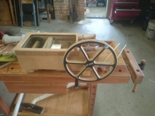
Figure 2 — Same input, two lineages. The crank organ inherits its form from the street organ-grinder — one operator, one slow rotary input — and its construction method from model engineering: a built-up crankshaft with con-rods and a pinned drive wheel, made on a home bench. This dive treats the drive as the model-engineering job it is.
1.7 What this dive owns, and what it defers
Because the crank is where every subsystem meets, a drive dive risks trespassing on half the program. The boundary is drawn deliberately and held throughout:
- This dive owns: the crank and handle; the crankshaft, throws, and con-rods as a linkage (not the bellows they drive); the driving wheel, drive cord/tyre/belt/gears, idler, friction clutch, and take-up spool as a transport (not the roll they pull); the RPM-to-tempo relationship, torque and effort, the flywheel’s smoothing role; and the whole electric-motor story — gearmotor selection, coupling, speed control, and automation.
- Wind Systems owns the feeder bellows, reservoir, spill valve, regulation, and the ~5 in H₂O working pressure. This dive stops at the con-rod’s little end.
- Encoding the Music owns the paper roll and cardboard book, the tracker bar, the 110 mm and 140 mm widths, and the hole map. This dive stops at the take-up spool.
- The Case, Façade & Figures (Dive 11) owns the moving-figure linkages. This dive marks the take-off on the crankshaft and stops there.
- The John Smith Universal Organ (Dive 5) and The Hobby Crank Organ (Dive 8) are the worked builds whose drive numbers this dive keeps identical — three feeders on a 120° crankshaft, the friction/idler/take-up drive, ~5 in H₂O. This is the cross-cut “drive” reading of those builds.
- Fairground & Dutch Street Organs (Dive 14) owns grand-machine drive — spring and clockwork motors, large electric drives, and self-playing fairground mechanisms. This dive touches those only as context and points there.
Holding these lines keeps the dive tight and keeps the program non-repetitive: the same 5 in H₂O figure, the same 110 mm roll, the same 120° crankshaft appear in several dives, always with the same value, each dive developing the part it owns.
1.8 Roadmap — Vols 2 through 7
The remaining six volumes work outward from the crankshaft, from mechanism to power to control to reference.
-
Vol 2 — The Crank & Drivetrain. The mechanics part by part: the crank throw (stroke = 2 × throw), the crankshaft (three-lobed at 120° for three feeders; built-up 8 mm steel in pillow blocks — jsart129, jsart57), the con-rods to the feeders (cross-ref Wind Systems), and the music branch — driving wheel → friction tyre / 5 mm PU drive cord / grooved wheel / gears → idler → take-up spool, with the slipping friction clutch (jsart57/80/15/120, en_materiaal, en_20Hoffle2). The part-level “how it is built” volume.
-
Vol 3 — Speed, RPM & Tempo. The crank turns slowly (RPM “minimal,” jsart88; ~40–70 rev/min (est.)); the tempo relationship tempo = π · d · n / s (paper speed ÷ beat spacing) with tempo ∝ crank RPM; the take-up-drum-diameter tempo creep through a roll and why the friction clutch and the operator’s steady hand — not a fixed gear number — govern tempo. Recomputed worked (est.) examples, and the human-factors headline that steady cranking is a real, learned skill.
-
Vol 4 — Torque, Effort & the Flywheel. τ = F · r (the handle length is the moment arm and the mechanical advantage); the gear/pulley math (ω_out = ω_in · (T_driver / T_driven), torque inversely, checked against jsart88’s 1:1 and jsart61’s ~3:1); what makes an organ hard to crank (the lumpy pulsating feeder load, reservoir pressure × feeder area, friction); and how a flywheel / heavy winding wheel plus the reservoir smooth the lumpy torque so the crank turns evenly.
-
Vol 5 — Electric-Motor Drive. The documented conversion (jsart110, Ronald Walters): a 12 VDC motor with a variable-speed DC drive and a separate 12 V battery, driving a Senior 20 and its motorised rewind, tested with a gearmotor and a 12 V scooter motor; why a gearmotor (a bare DC motor runs at thousands of RPM, so a gearbox trades speed for torque down to the crank’s tens of RPM); the coupling through the same grooved driving/winding wheel the hand crank uses (jsart129 — the groove is “for a motor drive,” fitted with an 8 mm motor coupling); and matching the hand-crank speed so the fixed bellows/take-up ratios keep the designed tempo.
-
Vol 6 — Speed Control & Automation. PWM / variable-speed control (duty cycle → average voltage → average speed; the low-duty stall floor; the whine-versus-torque frequency trade); motorised rewind (jsart110/84 — the boring high-turn job the hand hates); and the automation spectrum — hand-crank → motor-assisted crank (jsart110) → fully automatic roll-player (jsart138) → MIDI (en_31toets). The authenticity-versus- convenience trade is put as a genuine trade, not a verdict.
-
Vol 7 — Reference & Cheatsheet. Gear-ratio and RPM-to-tempo tables (with the tempo = π · d · n / s formula and worked (est.) values); a motor-selection guide (gearmotor RPM/torque, PWM controller, 12 V battery); a drive-form comparison (friction tyre / grooved wheel + cord / gear-pin clutch); a glossary; a cross-index to Vols 1–6 and the sibling dives; and a bibliography.
The through-line is the thesis this volume set: one slow rotation of the handle, distributed by a single shaft into wind, music, and motion. Understand that split — what drives what, how fast, and against how much load — and the whole instrument, from the con-rod’s little end to the choice of a 12 V gearmotor, follows from it.
Comments (0)