Turning The Crank · Volume 5
Turning the Crank — Vol 05: Electric-Motor Drive
The previous volumes treated the crank as a thing turned by a human arm. This one removes the arm. The question is narrow and practical: how does a builder take a small hand-cranked busker or street organ — one already built to be turned by hand — and drive it instead with an electric motor, without disturbing anything else about how it plays? The good news for the hobbyist is that the job has been done and documented, that it reuses the drive interface the hand already used, and that the parts are cheap and off-the-shelf. The subtle news is that “matching the hand” means matching a speed, in revolutions per minute, and that getting that one number right is what keeps the wind, the paper, and the tempo all in the relationship the instrument was designed around.
The volume works outward from the one documented conversion. Section 1 lays out the recipe of record — a 12 V DC motor, a variable-speed DC drive, and a separate 12 V battery, driving a John Smith Senior 20 and its motorised rewind (jsart110, Ronald Walters). Section 2 answers why a gearmotor and not just a motor, with the speed-for-torque trade a gearbox makes. Section 3 shows the coupling: the motor drives the same grooved driving/winding wheel the hand crank uses, because that wheel was designed to accept either (jsart129, David Briggs). Section 4 is the timing argument — set the controller to the RPM that gave the right tempo by hand, and the fixed internal ratios keep the wind and paper in step. Section 5 is the bench work: mounting the motor, the battery box, belt tension, and switching between hand and motor. The detailed treatment of how a controller varies speed — PWM, duty cycle, the stall floor — is Vol 06’s subject and is only named here; the gearmotor torque arithmetic belongs to Vol 04 and is used, not re-derived.
Voice / units / sourcing note. Electrical quantities are given in volts (V) and amperes (A); rotational rates in rev/min (RPM); torque in newton-metres (N·m); and reduction ratios as i : 1. The one documented conversion — a 12 VDC motor with a variable-speed DC drive and a separate 12 V battery — is jsart110 (Ronald Walters). The grooved driving/winding wheel cut “for a motor drive,” and the handle fitted with an “8 mm motor coupling,” is jsart129 (David Briggs). These are two different contributors solving two halves of the same problem and must not be cross-attributed. Every motor RPM, torque, and reduction-ratio figure used in a worked example is illustrative and marked (est.); no hobby source states motor internals. The exact relationships — a gearbox trades speed for torque, and matching one shaft speed matches all three driven functions — are stated exactly.
5.1 The documented conversion
There is one anchor for the whole volume, and it is worth quoting closely because it sets both the parts list and the design intent.
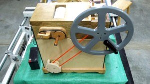
Ronald Walters’ article Motorising the John Smith Senior Organ describes adding a 12 VDC motor with variable speed control to power the Senior 20 organ, an addition that “also allows motorised rewinding of the music roll.” The crucial procurement note is that “the motor and the DC motor drive are readily available on eBay,” and that “the 12-volt battery is in a separate battery carrier” (jsart110, Ronald Walters). The article is built around a series of demonstrations — an Experimental Gearmotor Drive, a 12 V Scooter Motor Test, an operational 12 V motor drive, a 12 V motor-powered music-roll rewind, and the 12-volt battery box — which together map the whole conversion from bench experiment to a running, self-winding organ.
Read as an engineering recipe, the conversion has exactly three functional blocks plus the interface to the organ:
- A 12 V DC motor — the prime mover, chosen at 12 V so it runs from a battery and from cheap DC controllers. Walters tests two candidates: an experimental gearmotor and a 12 V scooter motor (jsart110). Section 2 explains why the gearmotor form is the natural fit and what the scooter motor has to do to join it.
- A variable-speed DC motor drive — the controller that sets how fast the motor turns. Walters specifies it only as a “variable speed control … readily available on eBay” (jsart110); the class of device is a small DC speed controller, and how it varies speed (pulse-width modulation of the average armature voltage) is Vol 06’s subject. Here it matters only that the operator can dial the output shaft to a chosen RPM and hold it there.
- A 12 V battery in a separate carrier — the power source, deliberately kept in its own box rather than built into the organ (jsart110). A separate carrier keeps the battery’s mass and its acid or lithium chemistry out of the instrument case, keeps the organ’s weight and balance close to the hand-cranked original, and lets the battery be charged, swapped, or left behind (for hand play) independently.
The fourth element is not a new part at all: the drive interface into the organ is the one the hand crank already used. That is the pivot of the whole design and the subject of Section 3. The conversion does not re-engineer the drivetrain downstream of the driving wheel — the con-rods to the feeder bellows, the friction/cord drive to the take-up spool, the whole mechanism of Vol 02 — it simply replaces what turns the driving wheel, swapping a hand for a motor at the same wheel.
That the same motor also powers the rewind is not a side note; it is half the argument for motorising. Rewind is the high-turn, low-value job — spinning the roll back onto the supply spool after a tune — and it is exactly the part a hand hates. The music-roll rewind pulls the played paper back the way it came; the roll medium and the direction of pull are Encoding the Music’s to own, and this volume cross-references them only to note that the same 12 V motor drives both playback (slow, loaded) and rewind (fast, unloaded) from one installation (jsart110). Vol 06 develops the automation side of that — motorised rewind as the first step up the “take the human out of the loop” ladder.
5.2 Why a gearmotor: trading speed for torque
The first mistake a newcomer makes is to picture a motor spinning the crank directly. It will not work, and the reason is a mismatch of two orders of magnitude between where a DC motor likes to run and where the organ needs to be turned.
5.2.1 The mismatch
A bare permanent-magnet DC motor of the sort sold cheaply for hobby and scooter use runs fast and light: several thousand RPM (est. ~2,000–4,000 RPM) at its rated 12 V, at a correspondingly small torque. The organ’s crankshaft, by contrast, is a slow, torquey shaft — Vol 03 established that it turns at only tens of RPM (est. ~40–70 RPM), the “minimal” crank speed noted in jsart88 — and that it must overcome the lumpy pulsating load of the feeder bellows, the friction of the paper drive, and bearing drag (the torque budget is Vol 04’s). Bolt a 3,000 RPM motor straight to a shaft that wants 60 RPM and two things go wrong at once: the speed is ~50× too high, and the raw motor torque at that speed is far too small to turn a loaded organ. The motor would either stall or, if it could spin the shaft, would play the tune at a ludicrous, unlistenable speed.
5.2.2 What a gearbox does
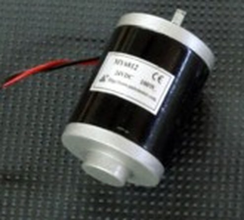
The fix is a reduction gearbox between the motor and the load — which is precisely what a gearmotor is: a DC motor with a reduction gearbox built onto its output shaft, giving a low output RPM at a high output torque. A gearbox trades one for the other by its reduction ratio i (input turns per output turn):
ω_out = ω_in ÷ i (output speed is the motor speed divided by the ratio)
τ_out = τ_in × i × η (output torque is the motor torque multiplied by the ratio, times the gearbox efficiency η ≤ 1)
Speed comes down by i; torque goes up by i, less the efficiency losses η (friction in the gear mesh and bearings — a modest spur or planetary train might run η ≈ 0.7–0.9, est.). This is the same speed-for-torque relation used throughout Vol 04 for the crank’s own gear and pulley ratios; here it runs in the reduction direction. The two effects are exactly what the organ needs: bring the thousands of RPM down into the tens, and multiply the small motor torque up into the newton-metres a loaded crank demands.
Worked example (all inputs est.). Suppose a small 12 V motor spins at 3,000 RPM (est.) and delivers 0.05 N·m (est.) of torque near that speed, and the organ wants its driving wheel turned at 60 RPM (est.). The reduction needed is
i = 3,000 ÷ 60 = 50 : 1 (est.)
and the torque at the output shaft, taking η = 0.75 (est.), is
τ_out = 0.05 N·m × 50 × 0.75 = 1.875 N·m (est.)
which comfortably exceeds the ~1.2 N·m a hand applies at a 60 mm crank handle in the Vol 04 example — i.e. a 50 : 1 gearmotor turns a light 12 V motor into a shaft that out-muscles the human hand while spinning at the human’s pace. The reduction ratio is the single number that does both jobs; pick it to land the motor’s natural speed on the crank’s natural speed, and the torque takes care of itself.
5.2.3 Where a scooter motor sits
This is why Walters’ two test motors — the experimental gearmotor and the 12 V scooter motor (jsart110) — are both sensible choices, and why they are not quite the same kind of thing. A purpose-built gearmotor arrives already reduced: its output shaft is the low-RPM, high-torque shaft the organ wants, and a 12 V scooter or wheelchair gearmotor in particular is designed to move a person at a walking pace, so its geared output already sits in the low-RPM, high-torque region (its intended job is close kin to turning a stiff crank). A bare scooter motor without its reduction, by contrast, is a fast, light armature and would still need a reduction stage (its own chain-and-sprocket, a pulley step-down, or a worm box) to reach the crank’s tens of RPM. Either way the design target is the same: arrive at the driving wheel spinning at the tens-of-RPM the hand achieved, with torque to spare. Whether that reduction lives inside a gearmotor’s housing or in an external belt/chain step-down is a packaging choice; the ratio arithmetic above is identical.
Figure 5-1. The gearmotor speed-for-torque trade. A 12 V DC motor spins at several thousand RPM at low torque; a reduction gearbox of ratio i divides the speed by i and multiplies the torque by i (times efficiency η), landing the output shaft in the crank’s tens-of-RPM band while giving it the torque a loaded organ needs. Choosing i to place the motor’s natural speed on the hand-crank speed band (est. ~40–70 RPM, jsart88) is the whole selection problem. Motor RPM and torque are illustrative (est.); ω_out = ω_in ÷ i and τ_out = τ_in × i × η are exact.
5.3 The coupling: one wheel, hand or motor
The elegance of the documented approach is that the motor does not get its own new place to attach. It drives the same grooved driving/winding wheel the hand crank uses — the wheel Vol 02 traced as the take-off from the crankshaft into the music transport. That this is possible is not luck; it is design, and it comes from a different contributor than the motor recipe.
5.3.1 A wheel designed to accept either
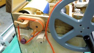
In Built-Up Crank, Glass Lid and Winding Handle, David Briggs describes making the winding handle for a Senior 20 from 17 mm Formply and notes two features that matter here directly: “the groove in the wheel is for a motor drive,” and “the handle is attached using an 8 mm motor coupling” (jsart129, David Briggs). Read those together and the intent is unmistakable. The winding wheel carries a groove so that a round drive belt from a motor can run in it; and the hand handle is fixed to the wheel’s 8 mm shaft through a motor coupling — the same class of shaft coupling a motor would use. The wheel was built from the start to be turned either by the hand handle or by a motor, through the one interface. A builder does not choose hand or motor at construction time and commit; the wheel accommodates both.
Concretely, that gives two ways to put the motor onto the wheel, and the wheel’s own features name each:
- A round belt in the groove. The groove exists “for a motor drive” (jsart129): a
round polyurethane belt — the same 4–5 mm round drive belting used throughout these
organs to drive the music spools (jsart120, Melvyn Wright;
en_materiaal) — runs from a small pulley on the gearmotor’s output shaft down into the wheel’s groove. The belt lets the motor sit off the wheel’s axis, wherever there is room in the case, and it provides a built-in reduction stage (a small motor pulley driving the larger grooved wheel steps the speed down further, ω_out = ω_in × d_motor ÷ d_wheel). - A direct shaft coupling. The handle is fixed with an “8 mm motor coupling” on an 8 mm shaft (jsart129). A motor whose output is also an 8 mm shaft can be joined to the wheel’s shaft with the same coupling — the motor takes the place of the hand handle on the wheel’s own axis. This is the tidiest arrangement where the gearmotor’s output speed is already the wheel’s target speed (no belt reduction needed).
Either way, the motor drives the wheel, the wheel drives everything the hand drove, and the choice of hand or motor is made at the coupling, not in the drivetrain.
5.3.2 The schematic
Putting Sections 1–3 together gives the complete drive: the 12 V battery in its separate carrier feeds the variable-speed DC drive (jsart110); the drive powers the gearmotor (Section 2); and the gearmotor turns the grooved driving/winding wheel — the same wheel the hand crank turns — through a belt in the groove or a coupling on the 8 mm shaft (jsart129). Downstream of that wheel, nothing changes: the crankshaft still drives the feeder bellows through the con-rods, and the driving wheel still advances the take-up spool through the friction/cord drive of Vol 02.
Figure 5-2. The motor-drive schematic. A 12 V battery in a separate carrier feeds a variable-speed DC drive, which powers the gearmotor; the gearmotor turns the grooved driving/winding wheel through a round belt in the groove (the battery + drive recipe is jsart110, Ronald Walters; the grooved wheel and 8 mm motor coupling are jsart129, David Briggs). The same wheel accepts the hand crank through its 8 mm coupling, so the drive is hand or motor at one interface. Downstream — crankshaft, con-rods to the feeder bellows, and the take-up spool — is unchanged from Vol 02.
5.4 Matching the hand-crank speed keeps the timing
With the parts chosen and the coupling made, the entire tuning of the conversion reduces to setting one number: the RPM at which the motor turns the driving wheel. Get that right and the organ plays exactly as it did by hand. The reason is the most important conceptual point in the volume, and it follows directly from the mechanism.
5.4.1 One speed sets all three functions
Recall from Vol 02 that the crankshaft does two jobs from one rotation — it raises the wind (throws → con-rods → feeder bellows) and advances the music (driving wheel → friction/cord drive → take-up spool) — and that both are geared off the same shaft by fixed ratios built into the mechanism. The feeders pump once per feeder per crank revolution; the take-up spool turns at its fixed ratio to the crank; the paper advances accordingly. None of those ratios changes when a motor replaces the hand. They are mechanical constants of the instrument.
The consequence is decisive: because the three functions are locked to the driving wheel by fixed ratios, matching the wheel’s speed matches all three at once. Set the motor to turn the driving wheel at the same tens-of-RPM the hand achieved, and:
- the feeder bellows pump at the same rate — so the wind delivery matches what the reservoir and pipes were voiced for (the wind physics belong to Wind Systems; here it matters only that the pump rate is preserved by preserving the crank RPM);
- the take-up spool advances the paper at the same speed — so the paper linear speed v is what it was by hand; and
- the tempo is therefore unchanged. From Vol 03, tempo = π·d·n ÷ s, where the take-up speed n is a fixed multiple of the crank/driving-wheel speed. Hold the driving-wheel RPM and every term is what it was by hand, so the BPM is what it was by hand.
There is no need to match three things separately, and no way to get them out of step by matching only one. This is why the conversion can be so light-touch: it changes the prime mover without touching any of the ratios that define how the organ plays.
5.4.2 Setting the controller by ear
Practically, the builder finds the right speed the same way the hand did — by tempo. The procedure is:
- Play a known tune by hand and settle on the crank cadence that gives the right tempo (Vol 03: the hand is the tempo control; a comfortable playing tempo corresponds to a crank turning at an est. ~40–70 RPM).
- Fit the motor and run it up on the variable-speed drive until the tune plays back at that same tempo. Because tempo ∝ driving-wheel RPM, matching the tempo is matching the RPM — the operator does not need to measure shaft speed with a tachometer; the ear resolves it directly.
- Note that controller setting. That duty-cycle/speed setting is now the organ’s “correct tempo,” reproducible run to run — which is precisely the advantage a motor has over a hand: it holds the RPM, and therefore the tempo, perfectly steady, with none of the drift Vol 03 documents as the hand’s besetting difficulty.
The tempo the motor holds is only as right as the RPM it is set to; if the drive is nudged, the tempo moves with it — but a controller, once set, does not tire or rush. The authenticity trade this creates — a perfectly steady motor tempo versus the living, hand-driven rubato — is Vol 06’s to weigh; this volume only establishes that the conversion can reproduce the hand’s tempo exactly, by matching the one speed.
5.4.3 Torque headroom at the matched speed
Matching the speed is necessary but not sufficient: the motor must also deliver enough torque at that speed to turn the loaded organ. This is where Section 2’s reduction ratio earns its place. The load the driving wheel must overcome — the lumpy feeder torque, paper drag, and friction — is the same torque budget the hand faced, developed in Vol 04. A correctly chosen gearmotor lands its high-torque output shaft on the crank’s low-RPM band with torque to spare (the worked example gave ~1.9 N·m est. against a ~1.2 N·m est. hand demand), so it turns the organ steadily through the hard part of each feeder stroke without bogging. If a motor is geared for the right speed but is undersized for the torque, it will slow or stall at the bottom of the compression stroke — the same place the hand feels the load worst — and the tempo will lurch. The cure is more reduction (a larger i, buying torque at the cost of top speed) or a larger motor; the gearmotor selection is, in the end, a joint speed-and-torque fit, and Vol 04 owns the torque half of that arithmetic.
5.5 Practical installation
The conversion’s parts are cheap and few; the craft is in mounting them so the motor drive is solid, the battery is out of the way, the belt is correctly tensioned, and the operator can still fall back to the hand crank. The following are practical notes, consolidated from the documented conversion (jsart110) and the wheel-and-coupling design (jsart129).
5.5.1 Mounting the motor
The motor must be held rigidly relative to the driving wheel, because any flex changes the belt tension or the coupling alignment as the load pulses. Two arrangements follow from the two coupling options of Section 3:
- Belt drive (motor off-axis). The gearmotor is bolted to a bracket or a sub-plate fixed to the organ’s frame, positioned so its output pulley aligns with the plane of the driving wheel’s groove and stands at a fixed centre distance. This is the more forgiving arrangement: the belt tolerates small misalignments, and the motor can be tucked wherever the case has room. A slotted bracket lets the centre distance be adjusted to tension the belt (Section 5.3).
- Direct coupling (motor on-axis). The gearmotor’s 8 mm output shaft is joined to the driving/winding wheel’s 8 mm shaft with a motor coupling — the same 8 mm coupling class the hand handle uses (jsart129). This demands good axial alignment (the motor shaft and the wheel shaft must be collinear, or a flexible/Oldham coupling used to absorb the small error), but it is compact and has no belt to tension. It suits a gearmotor whose output speed already equals the wheel’s target speed, since it provides no further reduction.
In both cases the motor mount must react the drive torque without shifting: at ~1.9 N·m (est.) of output torque a mount that flexes will let the belt tension or shaft alignment wander with each feeder stroke.
5.5.2 The battery box
Walters keeps the 12 V battery in a separate battery carrier (jsart110), and the reasons are worth making explicit as design guidance:
- Weight and balance. A 12 V battery is heavy; built into the case it would change the organ’s mass and balance from the hand-cranked original. In its own carrier the instrument keeps close to its designed weight distribution.
- Serviceability. A separate carrier lets the battery be charged, swapped for a fresh one, or upgraded (e.g. from lead-acid to a lithium pack of the same nominal 12 V) without opening the organ.
- Reversibility. Leave the battery box behind and fit the hand handle, and the organ is a pure hand-cranked instrument again — the separate carrier is what makes the motor drive an addition rather than an irreversible conversion.
Run the supply from the carrier to the variable-speed drive with a fuse close to the battery (a short-circuit in the motor wiring at 12 V can pass a very large current from even a small battery), a master switch, and adequately sized conductors for the motor’s stall current.
5.5.3 Belt tension
Where a round belt runs in the groove (Section 3.1), tension is a genuine adjustment. Too loose and the belt slips on the driving wheel under the pulsating feeder load — the tune drags and surges as the belt grabs and releases; too tight and it loads the motor and wheel bearings needlessly and can whine. The belt should be just tight enough that it does not slip at the hardest part of the feeder stroke, and no tighter. Round polyurethane belting (jsart120) is heat-welded to a chosen length, so tension is set by the welded loop length against the fixed motor-to-wheel centre distance, or trimmed with a slotted motor bracket that moves the motor a few millimetres to take up slack. A belt run offers a convenient place to add reduction as well: a small motor pulley into the larger grooved wheel steps the speed down further, which can bring an over-fast gearmotor into the crank band without changing the gearbox.
5.5.4 Switching between hand and motor drive
The whole point of the shared grooved/coupled wheel (jsart129) is that a builder need not give up hand play. In practice the changeover is mechanical:
- On a belt drive, slipping the round belt off the groove frees the wheel for the hand handle; refitting the belt returns it to the motor. Because the belt is a simple loop, this is a few-seconds job.
- On a direct coupling, the motor coupling is undone and the hand handle fitted to the same 8 mm shaft in its place — the handle and the motor are interchangeable at the one coupling (jsart129).
The comparison below summarises what the two drives offer the operator; it is a genuine trade of effort and steadiness against presence and authenticity, developed as such in Vol 06.
Table 1 — 5.4 Switching between hand and motor drive
| Aspect | Hand crank | Electric-motor drive |
|---|---|---|
| Prime mover | Operator’s arm | 12 V DC gearmotor (jsart110) |
| Speed control | Operator’s cadence (Vol 03) | Variable-speed DC drive setting (jsart110; Vol 06) |
| Tempo steadiness | Wobbles; “a chore” to hold steady (Vol 03) | Rock-steady once set (holds RPM exactly) |
| Effort | Continuous, tiring on long play | None; battery does the work |
| Rewind | Slow hand-cranking of the roll | Motorised, fast, unloaded (jsart110; Encoding the Music) |
| Interface to organ | 8 mm handle on the winding wheel (jsart129) | Belt in groove or 8 mm coupling on the SAME wheel (jsart129) |
| Reversible? | — | Yes: remove belt/coupling + battery box, refit handle |
| Character | Living, hand-driven rubato and busker presence | Removes effort and wobble; also removes the hand (Vol 06) |
Table 5-1. Hand crank versus electric-motor drive on the same organ. The two share the one grooved/coupled driving wheel (jsart129), so a builder can move between them; the choice trades effort and steadiness against the living hand, weighed in Vol 06.
5.6 Summary
Converting a small hand-cranked busker organ to electric drive is, at heart, a matter of replacing the arm at one wheel and setting one speed. The documented recipe and the design that makes it clean come together as follows:
- The conversion of record is a 12 VDC motor with a variable-speed DC drive and a separate 12 V battery carrier, driving a John Smith Senior 20 and its motorised rewind; the motor and drive are cheap eBay items, and the conversion was tested with an experimental gearmotor and a 12 V scooter motor (jsart110, Ronald Walters).
- A gearmotor is the right form because a bare DC motor runs at thousands of RPM while the crank wants tens; a reduction gearbox trades speed for torque — ω_out = ω_in ÷ i, τ_out = τ_in × i × η — bringing the motor into the crank’s low-RPM band while multiplying its torque into the newton-metres a loaded organ demands (Vol 04 owns the torque budget). A 12 V scooter/wheelchair gearmotor already sits in that range.
- The coupling reuses the hand’s own interface. The driving/winding wheel carries a groove cut “for a motor drive,” and the handle is fixed with an “8 mm motor coupling,” so the same wheel takes either a round belt from a motor or the hand handle (jsart129, David Briggs). The choice of hand or motor is made at the coupling, not in the drivetrain (Vol 02 downstream is untouched).
- Matching one speed matches everything. Because the feeder pump rate and the take-up/paper speed are locked to the driving wheel by fixed ratios, setting the motor to the tens-of-RPM the hand achieved preserves the wind delivery, the paper speed, and — via tempo = π·d·n ÷ s (Vol 03) — the tempo, all at once. The builder sets the controller by ear to the tempo the hand gave, and the motor then holds it perfectly.
- The installation mounts the motor rigidly (belt off-axis or direct 8 mm coupling), keeps the battery in a separate fused carrier for weight, service, and reversibility, tensions the belt to just short of slip, and leaves the hand crank available at the same wheel.
The detailed treatment of how a variable-speed drive sets and holds that RPM — PWM, duty cycle, the low-duty stall floor — and where the motor sits on the automation spectrum, from motor-assisted crank to fully self-playing, is Vol 06 (Speed Control & Automation), along with the authenticity-versus-convenience trade this volume has only named. The gearmotor torque arithmetic is Vol 04; the tempo relationship it must preserve is Vol 03; the wheel it drives is Vol 02; and the roll the motorised rewind pulls back is Encoding the Music’s.
Comments (0)