The Case Facade And Figures · Volume 3
The Case, Façade & Figures — Vol 03: Layout & Packaging
Vol 02 treated the case as an object in its own right — the structural, mildly acoustic box, its wood, its wall thickness, the two lids, the leak-tested groundplate, and the cart it rides on. This volume asks the harder question the box exists to answer: how do the pipework, the wind system and the music medium all fit inside it at once, and still leave a person able to carry it, crank it, tune it, and stand a moving figure on top?
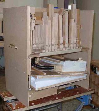
That is a genuine spatial-engineering problem. A small hand-cranked busker or street organ packs three bulky, awkward subsystems — each with its own service access, its own moving parts, and its own preferred orientation — into a box in the size band ~12 × 8 × 10 in to ~24 × 8 × 10 in (30 × 20 × 15 to 60 × 40 × 30 cm) (jsart98, Wallace Venable). Nothing about that volume is generous. Every part competes for the same litres of air, and a decision that helps one subsystem (raise the chest for a straight wind run) hurts another (now the bass pipes foul the lid). This volume is about the arrangement — the stacking order, the access cuts, the clearances, and the weight balance — and it defers each subsystem’s internals to the dive that owns it.
Scope and framing. Internal layout varies with every design, so this volume teaches the principle and marks specific fixings and positions (est.) where a general hobby case is described rather than one documented build. It does not re-derive wind pressure or bellows geometry (see the Wind Systems dive), the roll/book/MIDI mechanism (see Encoding the Music), pipe construction (see Building Organ Pipes), or tuning method (see Tuning & Voicing). It cross-refers Vol 02 for the box itself and Vol 06 for the figure drive that the pipe-mitring in §6 exists to clear. Imperial source figures are kept and the metric added; wind pressure at this scale sits near 5 in H₂O (127 mm ≈ 1.245 kPa) and is quoted only as context.
3.1 What has to coexist inside the box
Strip a small crank organ to its functional blocks and three of them dominate the internal volume. Each wants space, and each wants that space in a particular place relative to the others.
- The pipework. One or more ranks standing on the wind chest: a front melody rank (short pipes, often the pan-flute/piccolo voice shown on the façade), and the bass pipes, which are the tallest and most space-hungry objects in the whole instrument. On a 20-note Carl Frei/Raffin scale the longest stopped bass pipe still stands well above the melody rank, and an open bass pipe taller still. Where those tall pipes go — and whether they must be mitred (folded) to fit — sets the height of the box more than anything else. Note count is not pipe count: 20 notes across several registers means far more than 20 pipes on the chest.
- The wind system. The feeder bellows (pumped off the crankshaft) that raise the wind, and the sprung reservoir/magazine bellows that store it and hold it to a flat pressure. Together they are a flat, wide, breathing assembly that wants to lie horizontally, low in the case, with an unobstructed rise-and- fall stroke. Their leathering, gusseting and spring-setting belong to the Wind Systems dive; here they are simply a box-within-the-box that must not be crushed, blocked, or leaked by anything packed around it.
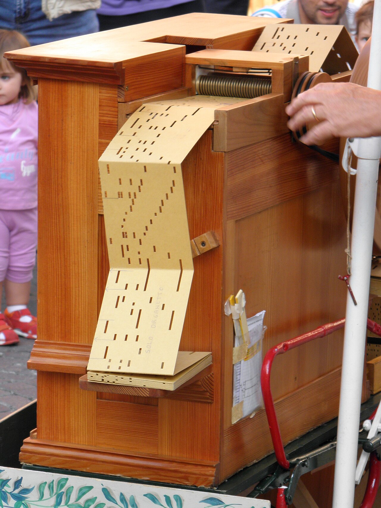
- The music medium. The paper-roll frame (supply reel, take-up reel, and the reading face that runs the perforated roll over the key/pallet openings) — or, in a book organ, the book mechanism (the keyframe the folded cardboard book is drawn through), or, in a MIDI conversion, a solenoid rail and a small controller. Whichever it is, it lives at the playing position: the operator must be able to load, thread, tension and change it, so it faces outward or upward at a reachable point. The medium itself — punching rolls, folding books, MIDI — is the Encoding the Music dive.
Two more things thread through all three: the crank and driveshaft, which enters through one side wall and must drive both the feeder crankshaft and the music transport from a single handle; and the operator’s access, the cuts and lids that let a human reach the crank bearings, the reel, and the pipe feet for tuning without dismantling the instrument.
3.2 The subsystem map — where each thing sits, and whose dive owns it
The arrangement below is the common hobby stacking pattern. Treat the exact heights and fixings as (est.) for a general case; the relationships are what carry from build to build.
Table 1 — 2. The subsystem map — where each thing sits, and whose dive owns it
| Subsystem | Where it sits in the box | Preferred orientation | Owned by (cross-ref) |
|---|---|---|---|
| Wind chest (table/soundboard) | Upper middle — a horizontal slab spanning the box, pipes standing on it | Flat, level, with pallets/valves accessible from below | Wind Systems (chest & pallets); Building Organ Pipes (rank spacing) |
| Melody / front pipes | Front edge of the chest, low and outward, behind the façade opening | Standing, mouths facing the front opening | Building Organ Pipes; Façade (Vol 04) |
| Bass pipes | Tallest rank — back or ends of the chest, or laid/mitred if height-limited | Standing where headroom allows; mitred where it does not (§6) | Building Organ Pipes |
| Feeder bellows | Low, beside or below the reservoir, on the crankshaft side | Flat, hinged for a clear pumping stroke | Wind Systems |
| Reservoir / magazine | Below or behind the chest, feeding it a short wind trunk | Flat, spring-loaded, free to rise and fall | Wind Systems |
| Roll frame / book mechanism | Front playing position (front face or under the lifting lid) | Reels vertical or shallow-raked, reachable for loading | Encoding the Music |
| Crank + driveshaft | Along one side wall, entering through a bearing in that wall | Horizontal, coupled to feeder crank + transport | Wind Systems (drive); the John Smith Universal build (crank detail) |
| Fixed lid | Top, over the pipes — closes the pipe chamber, doubles as the figure platform | Flat, rigid enough to carry an automaton | This dive (Vol 06 for the figure) |
| Lifting lid | Top, over the crank/driveshaft end — hinged for access | Hinged, clears the driveshaft and reel | This dive; jsart14, Bernard Pilgrim |
Reading down the table, a shape emerges: a short vertical chain with the wind at the bottom, the chest across the middle, and the pipes standing on top, while the music medium and the crank run down one side and one face where the operator can reach them. The next section builds that chain from the floor up.
3.3 Stacking the box — the vertical chain
Figure 3-1. The signature packaging view: a small crank organ in side cross-section, front at the left. Wind (reservoir + feeder bellows) sits low; the chest spans the middle; short melody pipes stand at the front behind the grille-covered opening while the tall bass pipes stand at the back and set the box height; the roll frame occupies the front playing position; the crank and driveshaft run along the near side (shown dashed, into the view). The fixed lid over the pipes doubles as the figure platform; the lifting lid gives crank access (jsart14, Bernard Pilgrim; jsart98, Wallace Venable). Positions are schematic and vary by design (est.).
3.3.1 Wind at the bottom
The reservoir and feeders are the foundation of the stack for three reasons. They are the heaviest continuous mass in the instrument, so putting them low drops the centre of gravity (§8). They breathe — the reservoir rises and falls against its spring — so they need a clear vertical envelope that nothing else may intrude on. And they feed the chest directly above them through the shortest possible wind trunk; a short, fat, low-resistance run keeps the pressure steady and leaves less flexible ducting to leak or kink. The feeder bellows sit on the crankshaft side so the connecting rod from the crank reaches them without crossing the whole box. None of the bellows craft is re-derived here — see Wind Systems — but the layout rule is firm: give the wind system a protected, unobstructed, low volume and let everything else pack around it.
3.3.2 The chest across the middle, pipes on top
The wind chest is the datum plane of the whole layout: a horizontal slab spanning the box, with the pallet valves reachable from below (on the wind side) and the pipe feet standing on top. Its height is a compromise. Set it high and the wind trunk is short and the pipes get less headroom under the lid; set it low and the pipes have room but the wind run and the operator’s reach both lengthen. The pipes then stand on top in their ranks — the front melody rank low and forward so its mouths face the front opening (§5), and the bass rank wherever the height allows, typically at the back or across the ends where the case is deepest. The tallest bass pipe is the single object that dictates box height; when it will not stand, it is mitred (§6). Rank spacing, foot-hole sizing and pipe order are the Building Organ Pipes dive’s business; here the pipes are simply the tall freight that has to clear the lid.
3.3.3 The music medium at the playing face
The roll frame or book mechanism lives where a human hand can reach it every few minutes: at the front playing position, either set into the front face below the pipes or presented under the lifting lid. Its reels want to spin freely, its reading face wants to sit square over the chest’s key openings, and its take-up side wants slack to change a roll. That is a lot of demand for reachable space in a crowded box, which is why the medium usually claims one whole face or one end and pushes the pipework and wind to the opposite side. The transport is coupled to the same crank that pumps the feeders, so its drive take-off sits near the crankshaft. All of the medium’s internals — roll punching, book folding, MIDI solenoids, tracker-bar geometry — are the Encoding the Music dive; the layout concern is only that it be loadable and threadable in situ.
3.3.4 The crank and driveshaft down one side
A single handle does two jobs: it pumps the wind and it advances the music. The driveshaft therefore enters through a bearing in one side wall and runs the length of the box, throwing a crank for the feeder connecting rod and coupling to the music transport. Keeping it along one side (rather than through the middle) leaves the central volume clear for the wind-chest-and-pipes stack, and puts all the rotating, wearing, occasionally-oiled hardware under a single access lid. The crank handle itself is a show part on many builds — Ken Rawlings’ busker organ used an operating handle sawn from 1/8 in brass sheet to a swan-neck profile (jsart11, Ken Rawlings) — but its bearing and coupling detail belong to the drivetrain treatment in the Wind Systems dive and the John Smith Universal build.
3.4 Access — the two lids and what they cover
A crank organ is not a sealed box; it is opened constantly — to load a roll, to oil the crank, to touch up a pipe’s tuning, to reset a figure. The classic hobby solution splits the top into two lids with two different jobs, and the split is one of the most important layout decisions in the whole build (jsart14, Bernard Pilgrim).
- The fixed lid closes over the pipes. It seals the pipe chamber (so the ranks speak into a defined space and are protected in transit) and it doubles as the platform on which the automaton stands (jsart14). Because a figure and its drive linkage bear on it, it must be rigid and its position must be settled early: Bernard Pilgrim’s plans have the builder set the automaton’s travel before slotting the lid into place, so the figure’s motion is proven before the platform is fixed. The tie-in to the figure drive is the Vol 06 subject; the layout consequence is that the pipes underneath this lid must be short enough, or mitred enough, to clear both the lid and the linkage that passes under it (§6).
- The lifting lid covers the crank and driveshaft end — the drive rod, the driving wheels, and usually the roll reel. It is hinged for routine access (jsart14). Pilgrim notes practical touches from the same tradition: catches made from off-centre-drilled coins, and the drive taken from a rod off the driving wheel. Because this lid is lifted in use, the parts under it — reel, crank bearing, coupling — are the ones the operator services most; grouping them under one hinged panel is the reason the crank runs down one side (§3.4).
This two-lid arrangement is what makes the whole packaging scheme work: the noisy, oily, frequently-handled drivetrain and music medium live under a lid that opens, while the delicate, tuned, figure-carrying pipe chamber lives under a lid that stays shut. Get the division wrong and the operator ends up disturbing tuned pipes every time a roll is changed.
3.5 Keeping the front pipes speaking and visible
On a small busker or street organ the pipes on the front are usually the real speaking melody rank, not dummies — the pan-flute/piccolo voice on top with the wooden bass beneath, in the street-organ tradition, and, on the John Smith Universal, the walnut-fronted melody pipes that actually sound. (The speaking-vs-dummy distinction and the façade proportions are Vol 04’s subject.) The layout consequence is a real constraint: those front pipes must be positioned so their mouths face the front opening and are not boxed in.
Two things follow for the internal arrangement. First, the melody rank sits at the front edge of the chest, low and forward, with its mouths in the plane of (or just behind) the façade opening, so the sound projects out rather than being trapped against a solid front board. Second, whatever grille, fretwork or pipe-shade dresses the opening must stay acoustically open — pierced or fretted enough that it does not choke the mouths it covers (est.; this is an inference from the projection role, cross-ref the acoustics treatment in the How Organ Pipes Make Sound dive and Vol 02’s careful acoustic-role wording). The broad guidance is simple: the front rank speaks through the opening, so pack nothing solid across its mouths and leave the grille open. Voicing those front pipes so they balance is the Tuning & Voicing dive; the layout job is only to give them a clear line to the front.
3.6 Mitring bass pipes to clear moving parts
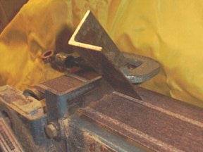
The tallest bass pipes are the hardest freight to stow, and the moving-figure linkage makes it harder still: the drive rod, pivot arm and connecting rod that run under the fixed lid to work an automaton pass exactly through the space the bass pipes want. The traditional fix is to mitre the offending pipe — fold it with a mitred (angled, usually 45°/45° to make a right angle) joint so the pipe’s acoustic length is preserved while its physical height, or its footprint, is bent out of the linkage’s way.
The documented case is the ‘Storybook’ animated front, where the bird figures are driven off the organ’s crankshaft through a horizontal connecting rod and a set of wing dowels, and the builder mitres the D and E♭ pipes at the bottom to clear the wing dowels (jsart38). The principle generalises: wherever a moving part — a dowel, a bell-crank, a pushrod — has to occupy the same region as a pipe, the pipe is folded around it rather than the mechanism being compromised. Mitring changes nothing an acoustician would hear if it is done cleanly (the air column is the same length), which is why it is the layout designer’s escape valve: it trades a little construction effort for the clearance that lets pipes and figure linkage share one crowded box. The pipe-making craft of cutting and sealing a mitre is the Building Organ Pipes dive; the figure linkage it clears is Vol 06.
Figure 3-2. Left: a full-length bass pipe standing on the chest fouls the horizontal wing dowel that drives the bird figure. Right: mitring the pipe at the bottom folds its foot aside, opening the clearance the reciprocating linkage needs while keeping the pipe’s speaking length unchanged — exactly the fix used for the D and E♭ pipes in the ‘Storybook’ front (jsart38). The fold direction and angle are schematic (est.); the acoustic length is what is preserved.
3.7 Routing wind and leaving tuning access
Two services thread invisibly through the packed box and both deserve a place in the layout, not an afterthought.
Wind routing. The wind path runs feeders → reservoir → chest, and the layout’s job is to keep it short, fat and gently curved. Long flexible trunks lose pressure and leak at every clip; sharp kinks throttle the flow. Putting the reservoir directly under the chest (§3.1) shortens the critical run to a stub. The 31-note build on hobbycrankorgan.com shows how seriously the wind path is taken as a structural element: it uses a layered groundplate with jigsawn air channels glued to the walls and papered over, then leak-tested before the pipes go on (en_31toets). That is wind routing built into the case itself rather than run in loose tube — and it makes the point that air channels compete for the same box space as everything else and must be planned with the stack. Pressures and bellows sizing are the Wind Systems dive.
Tuning access. Pipes drift; they will be tuned repeatedly over the instrument’s life. The layout must leave the pipe tops (for open pipes) or stoppers (for stopped pipes) reachable without pulling the chest. In practice this means the fixed lid must lift or unslot to expose the ranks, the ranks must be spaced so a hand and a tuning tool fit between pipes, and the tallest bass pipes — the ones most likely to be crammed into a corner or mitred — must still present their tuning point to a reachable spot. A pipe mitred hard against a wall to save space, with its stopper now buried, is a packaging failure even if it fits. The tuning method itself is the Tuning & Voicing dive; the layout obligation is simply to not bury the adjustment.
3.8 Weight distribution and centre of gravity
A crank organ is carried and it rides a cart, so where the mass sits matters as much as whether it fits. The size band is small — ~12 × 8 × 10 in to ~24 × 8 × 10 in (30 × 20 × 15 to 60 × 40 × 30 cm) (jsart98) — and a small pipe busker organ is light, on the order of ~10–15 kg (est.); the ~150 lb (≈ 60–70 kg) figure sometimes quoted on the hobby corpus is for a barrel piano, not a pipe busker organ (est.). Even at 10–15 kg, balance decides whether the instrument is a pleasure or a chore.
- Keep the centre of gravity low and centred. The wind system is the heaviest continuous mass, which is the second reason (after the short wind run) to put it low in the box (§3.1). Pipes are light; the chest and case walls are moderate; the bellows and any figure motor are the weights that swing the balance.
- Watch the figure on the lid. An automaton and its drive add mass high and often off-centre on the fixed lid. A dedicated figure with its own motor and battery is heavier still — the mechanical monkey is housed in a plywood box that slots into two brackets on the side of the organ (jsart55), deliberately hung low on the side rather than perched on top, precisely to keep a heavy motorised figure from raising and unbalancing the centre of gravity. Where a crank-driven figure must stand on the lid (Vol 06), keep it near the box’s long-axis centreline.
- Balance over the carry point and the cart axle. Lifting handles want to sit over the centre of mass so the box hangs level — Rawlings used “Magnet” kitchen-cupboard handles on the busker case (jsart11). On a cart, the mass wants to sit over or just behind the axle so the handles carry only a light, controllable down-force. The cart tradition itself — the 2-wheel hand-truck, the 4-wheel non-folding German cart (≈ $1000 from a builder), the folding box-cart, and the golf-trolley conversion — is Vol 02’s subject (jsart98); the layout concern is only that the packed box present a sensible, predictable centre of gravity to whatever carries it. The 31-note case simply bolts to its cart with two screws (en_31toets), which only works because its mass is already balanced over the cart.
3.9 A packing order that respects the constraints
The constraints above resolve into a rough order of decisions. It is not a build sequence (that is the Hobby Crank Organ dive’s Vol 03) but a layout order — the sequence in which the spatial commitments are best made so that an early choice does not strand a later subsystem.
- Size the box from the tallest bass pipe and the deepest bellows. The tallest standing pipe sets the interior height (or forces the mitring decision, §6); the reservoir’s breathing envelope sets a low reserved volume. Fix these first — they are the least negotiable.
- Place the wind system low and the chest directly over it. Short wind run, low centre of gravity, pallets accessible from the wind side (§3.1–3.2).
- Claim the front face for the melody pipes and the front opening. Mouths to the opening, grille kept open (§5).
- Give the music medium a reachable face or end at the playing position, coupled to the crankshaft side (§3.3).
- Run the crank/driveshaft down one side and group the drivetrain and reel under the lifting lid (§3.4, §4).
- Settle the figure and its linkage on the fixed lid, and mitre any pipe the linkage fouls. Prove the figure’s travel before fixing the lid (§4, §6; jsart14, jsart38).
- Verify the two services — a short leak-tested wind path (en_31toets) and reachable tuning points on every rank, including the mitred basses (§7).
- Check the balance — low, centred mass; handles and cart axle under the centre of gravity; figure near the centreline (§8).
Run in that order, the box that results is the one the opening premise promised: a carryable case in which the pipework, the wind system and the music medium coexist, the operator can reach every part that needs reaching, the front rank speaks out through the opening, and a moving figure stands and works on the lid — each subsystem’s internals left to the dive that owns it, and the arrangement alone the achievement of this one.
Cross-references: Vol 02 (the case as a box — materials, lids, cart); Vol 04 (the façade and speaking-vs-dummy display pipes); Vol 06 (moving figures and the crankshaft linkage the pipe-mitring clears). Sibling dives: Wind Systems (bellows, reservoir, pressure, drivetrain), Encoding the Music (roll/book/ MIDI), Building Organ Pipes (pipes and mitring craft), Tuning & Voicing (the tuning access this layout preserves), and How Organ Pipes Make Sound (the case’s acoustic role, stated carefully). Sources cited inline by article and author: jsart98 (Wallace Venable), jsart14 (Bernard Pilgrim), jsart38, jsart11 (Ken Rawlings), jsart55, en_31toets.
Comments (0)