Hammond B-3 · Volume 8
Hammond B-3 — Vol 08: Power, Recapping, the AO-28 Preamp & Percussion Circuit
This volume is the bench guide to the AO-28 preamplifier chassis: its eight-tube circuit topology, the console power supply, electrolytic-capacitor recap, the percussion circuit (V5–V7), and the matching transformer that hands tonewheel signals to the preamp input. Theory of operation — the signal path from matching transformer through the AO-28 to the 6-pin Amphenol — is established in Vol 02 §“From generator to output” and cross-referenced here rather than repeated. Death-cap removal, the B+ discharge procedure, and the variac ramp are fully described in Vol 06 §“Safety first: the death cap & B+” and §“Capacitor-discharge procedure” — those sections are prerequisites for any work described here. Leslie 122 amplifier recap is Vol 11; scanner and line-box service is Vol 10; key-contact service is Vol 09; the reference cheatsheet and tube tables are Vol 18.
Warn: The AO-28 power supply develops a B+ rail on the order of +200 VDC — lower than the Leslie 122’s approximately +415 VDC but fully sufficient to cause cardiac arrest or third-degree burns. Filter capacitors in this supply hold charge after power-off and after the mains cord is pulled. Before opening the AO-28 chassis, removing any component, or unsoldering any lead: discharge and verify 0 VDC per the procedure in Vol 06 §“Capacitor-discharge procedure.” Do not assume time alone has bled the supply.
8.1 The AO-28 at a glance
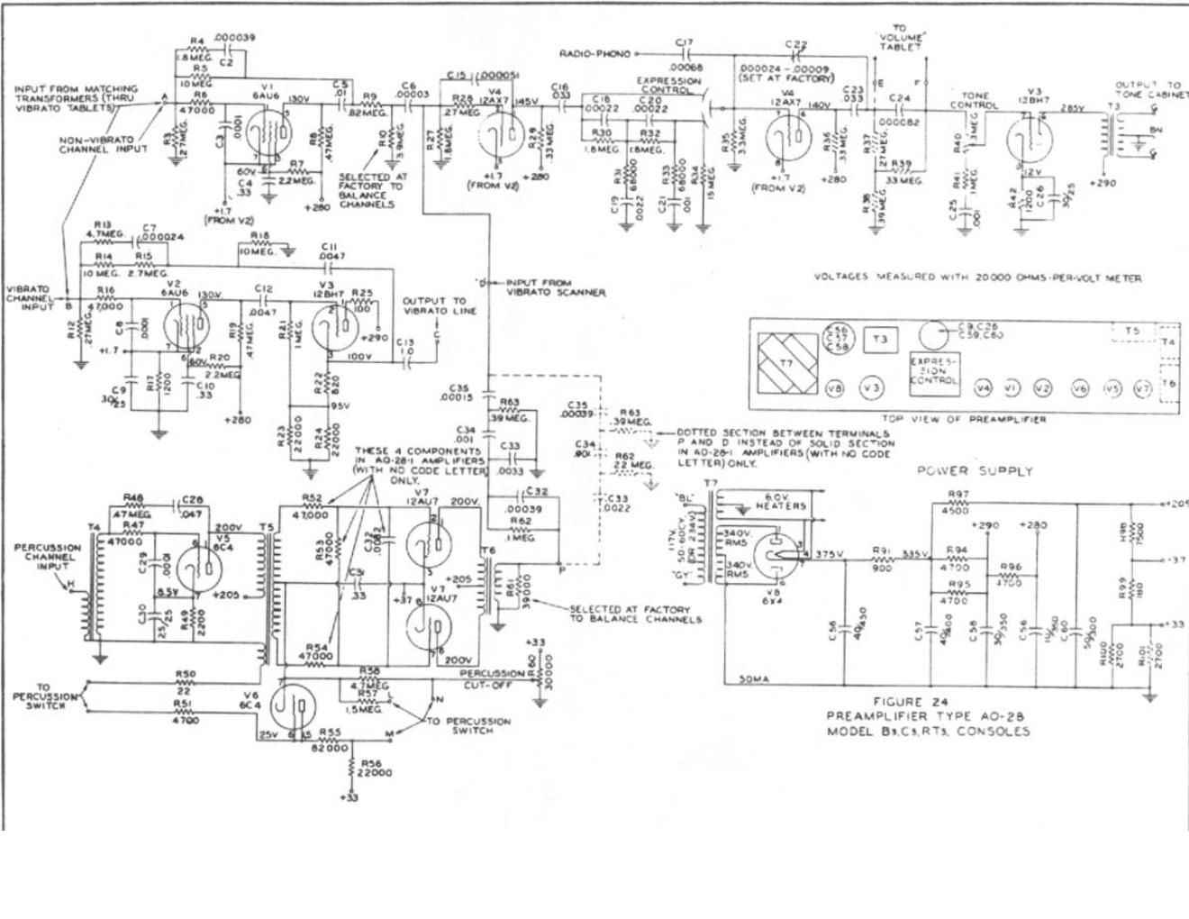
The AO-28 preamplifier is the sole active amplifier in the B-3/C-3/RT-3 console chassis — the instrument contains no power amplifier and no loudspeaker (Vol 01 §“What the B-3 is”). The AO-28’s eight tubes perform distinct signal-path roles: the first two receive the summed drawbar signal from the matching transformer (one per vibrato path), the third drives the output through the expression control, the fourth handles the volume/expression-pedal function, tubes five and six gate and key the percussion envelope, the seventh shapes the percussion decay, and the eighth rectifies the AC supply to the DC B+ rail. The AO-28 chassis also carries the vibrato line-box input terminals and the routing logic for the vibrato/chorus tablets (Hammond B-3/C-3 Service Manual; bentonelectronics.com, “Servicing the Hammond B-3 Type Pre-Amp”).
8.1.1 Tube complement
All eight tubes are confirmed against the Hammond B-3/C-3 Service Manual and the Benton Electronics AO-28 service article (bentonelectronics.com, “Servicing the Hammond B-3 Type Pre-Amp”):
Table 1 — AO-28 service article (bentonelectronics.com, "Servicing the Hammond B-3 Type Pre-Amp")
| Designation | Type | Function | Failure symptom if open/shorted |
|---|---|---|---|
| V-1 | 6AU6A | Non-vibrato (direct) input preamp — first gain stage for the non-vibrato path | Silence or severe attenuation on the direct (non-vibrato) manual signal |
| V-2 | 6AU6A | Vibrato input preamp — first gain stage for the vibrato/chorus path | Silence or attenuation on the vibrato signal path |
| V-3 | 12BH7A | Output stage and vibrato drive — delivers the mixed preamp output through the expression network; also drives the vibrato circuit | Weak or absent output across all drawbar settings; vibrato drive lost |
| V-4 | 12AX7A | Dual triode; volume-control / expression-pedal amplifier — implements the expression pedal’s level law | Expression pedal without effect; output stuck at one level |
| V-5 | 6C4 | Percussion preamp — first amplification stage in the percussion chain | Percussion absent or very weak |
| V-6 | 6C4 | Percussion keyer — gates the percussion circuit; the K-terminal voltage swing from +25–30 VDC to 0 VDC under key-press is controlled here | Percussion continuously on (V-6 shorted) or permanently off (V-6 open) |
| V-7 | 12AU7A | Voltage-controlled percussion decay amplifier — shaped by transformers T4, T5, T6 and the Fast/Slow capacitor | Wrong decay timing; no percussion attack envelope |
| V-8 | 6X4 | Rectifier — converts the secondary of the power transformer from AC to the approximately +200 VDC B+ rail; noted as “most prone to failure” among the eight | No B+ → no output from any stage; console powers on but produces silence |
Sources: bentonelectronics.com, “Servicing the Hammond B-3 Type Pre-Amp” (all eight tube designations and functional descriptions); Hammond B-3/C-3 Service Manual (schematic tube positions and circuit description). The 6X4 “most prone to failure” characterisation is per bentonelectronics.com.
Note: The B-3/C-3 AO-28 tube complement is commonly misquoted in secondary sources as “two 12AU7 + one 12BH7 + one 6X4” — a four-tube formulation that confuses the AO-28 with the smaller AO-29 used in spinet models. The correct B-3/C-3 AO-28 complement is eight tubes: 2×6AU6A, 12BH7A, 12AX7A, 2×6C4, 12AU7A, and 6X4. Do not retube with a four-tube kit.
8.1.2 AO-28 signal path — block diagram
The block diagram below traces the full AO-28 internal signal flow, from matching-transformer input through the two input-preamp paths, the vibrato switch, the output stage and expression control, the percussion branch, and the 6-pin Amphenol output. The percussion branch is a parallel path tapped off the input, not a series stage.
8.2 Power supply & safe discharge
8.2.1 The AO-28 power supply
The AO-28 power supply is a conventional full-wave tube-rectifier supply (6X4 twin-diode). The V-8 (6X4) rectifier tube converts the power-transformer secondary AC to the DC B+ rail that supplies all eight stages. The unloaded B+ in a healthy AO-28 is on the order of approximately +200 VDC (observed at V-7 pin 1, per bentonelectronics.com, “Servicing the Hammond B-3 Type Pre-Amp”); the exact rail voltage at each stage node is dependent on the unit’s specific revision and power-transformer specification. Filter capacitors C56–C59 smooth this rail; the values and voltage ratings of these capacitors are listed in §“Recapping” below.
This approximately +200 VDC rail is substantially lower than the Leslie 122 amplifier’s approximately +415 VDC rail (Vol 04 §“The amplifier & power supply”), but it is still lethal — a shock across 200 VDC at the skin resistances typical in a warm workshop can drive well above the approximately 10 mA threshold current for ventricular fibrillation (general tube-amp safety practice; bentonelectronics.com). Treat the AO-28 supply with the same respect as the Leslie amp.
The console’s B+ is the second hazard point in the rig after the Leslie 122. Both must be treated as charged until a meter confirms otherwise.
Warn: The AO-28 B+ rail — approximately +200 VDC stored on the filter capacitors — persists after power-off and after the mains cord is pulled. This voltage is sufficient to cause cardiac arrest. Before removing any component, unsoldering any lead, or contacting any point in the AO-28 chassis: follow the full capacitor-discharge procedure in Vol 06 §“Capacitor-discharge procedure” and confirm 0 VDC at every section of the filter cap bank. A multi-section cap can hold charge on a section the discharge path missed — re-measure all sections individually.
8.2.2 Discharge procedure (cross-reference)
The complete discharge procedure for the AO-28 and console power supply is in Vol 06 §“Capacitor-discharge procedure.” Summary of prerequisites and tools (do not start without reading the full procedure in Vol 06):
- DMM set to DC volts, 600 V range minimum.
- Discharge resistor tool: 10 kΩ to 25 kΩ wirewound, ≥ 10 W for the AO-28 B+ rail alone (≥ 25 W if the same discharge tool will also serve the Leslie 122’s higher rail — see Vol 11) (at +200 V across 10 kΩ the dissipation is V²/R = 200² / 10 000 = 4 W).
- Insulated clip leads, 1 000 V-rated.
- Insulated gloves, 1 000 V-rated.
For a 100 µF filter cap through 10 kΩ: τ = RC = 10 000 × 100 × 10⁻⁶ = 1.0 s; five time constants (5 s) reduces the voltage to below 1 % of initial. In practice, monitor the DMM until it reads below 5 VDC before touching any filter-cap terminal. Re-measure after any work pause — dielectric soak can recover a partial charge (Vol 06 §“Capacitor-discharge procedure”).
8.2.3 The 6X4 rectifier tube
The V-8 (6X4) is the most failure-prone tube in the AO-28 (bentonelectronics.com, “Servicing the Hammond B-3 Type Pre-Amp”). A failed 6X4 collapses the B+ rail completely, silencing all eight stages — a symptom that mimics a blown power-supply fuse or a shorted filter capacitor. The diagnostic sequence:
- With the AO-28 discharged and powered down, remove V-8 and test it in a calibrated tube tester (or substitute a known-good 6X4 from stock).
- If the 6X4 tests weak or emission-low, replace it. A 6X4WA (military-grade equivalent) is an acceptable substitution; confirm the pinout matches before installing.
- After fitting a new 6X4, ramp the console via the variac procedure (Vol 06 §“Powering up a long-stored instrument”) rather than applying full mains cold, in case the existing filter capacitors need reforming after a period of collapse.
Warn: A shorted 6X4 does not merely fail to rectify — it can damage the power transformer by presenting a direct short across the transformer secondary. If the 6X4 is found shorted (measured anode-to-cathode continuity): inspect the power transformer for signs of overheating before fitting a replacement tube and applying power.
8.3 Recapping
8.3.1 Why electrolytic capacitors fail
Every electrolytic capacitor in the AO-28 is now six or more decades old. The aluminium-oxide dielectric film is maintained by current — a capacitor stored unpowered for years loses part of its dielectric integrity. In normal operation, dried electrolytics present with:
- Increased equivalent series resistance (ESR): a healthy new electrolytic in this service class typically measures below 5 Ω ESR at audio frequencies; a dried-out part can read 10 Ω to 100 Ω or higher. High ESR causes the filter capacitor to fail its ripple-suppression role — ripple at 120 Hz (full-wave rectification via the 6X4 twin-diode) passes through the supply and appears at the output as mains hum.
- Reduced capacitance: the measured µF value falls below the nominal value. Loss of hold capacity on the B+ rail causes sagging B+ under load, which biases the tube stages away from their operating points and produces weak, thin, or distorted output.
- Leakage current: oxide breakdown allows DC leakage through the dielectric, which shifts bias on downstream tube grids and upsets operating points silently — no obvious noise, just degraded performance and shortened tube life.
Warn: ESR-test before wholesale replacement. A capacitor that measures low ESR and nominal capacitance is a good capacitor and does not need replacement. Replacing all capacitors indiscriminately wastes parts and introduces new solder joints — the weakest reliability link in point-to-point wiring. Test each electrolytic with a dedicated ESR meter (PEAK ESR70, Atlas ESR+, or equivalent; see Vol 06 §“Refurb toolkit”) and a capacitance meter, then replace only those that fail their ESR or capacitance check, or that test in-spec but are known failure-class parts on this chassis.
8.3.2 ESR-guided testing procedure
Tools required: ESR meter (capable of in-circuit measurement at low test voltage); capacitance meter or DMM cap function; work light; inspection mirror for deep chassis access; anti-static wrist strap; DMM (DC volts, confirmed 0 VDC at all B+ points before testing begins).
Prerequisites: mains off, cord unplugged, B+ discharged and confirmed at 0 VDC per Vol 06 §“Capacitor-discharge procedure.”
- Discharge the B+ rail per the full procedure in Vol 06. Confirm 0 VDC at every filter-cap section with the DMM before touching any capacitor terminal.
- Locate and label each electrolytic. The AO-28 carries several populations: the B+ filter caps (C56–C59, in or near the power supply section), low-voltage bypass caps for individual tube stages, and coupling caps elsewhere in the circuit. Use an inspection mirror to read the value and voltage rating from each capacitor body; record the value and its condition (any visible bulging, electrolyte residue, or distorted vent).
- ESR-test in circuit (low test voltage — the ESR meter’s built-in ≤ 1 V AC signal does not forward-bias any semiconductor or tube junction). Note the reading for each cap against the table below. For electrolytics above approximately 100 µF in this service class, an ESR below 3 Ω to 5 Ω is healthy; readings above 10 Ω are marginal; readings above 30 Ω or an open circuit indicate a failed part requiring replacement.
- Measure capacitance of any cap that fails ESR. A cap reading low ESR but less than 70 % of its nominal µF value has compromised dielectric and should be replaced.
- Inspect visually for physical damage: bulging top vent, brown or crystalline electrolyte deposits on the body or leads, or discolouration of the pcb or terminal strip in the vicinity. Any physically damaged cap is replaced regardless of the ESR reading.
- Replace failed or marginal caps per the filter-cap table in §“Filter-capacitor table” below and the recap procedure in §“Recapping procedure.” Replace like-for-like (same capacitance, equal or higher WVDC) — never fit an under-rated replacement into an HV rail.
8.3.3 Filter-capacitor table
The following values are the primary filter capacitors in the AO-28 power-supply section as identified from the Hammond AO-28 schematic and a period parts reference (Hammond B-3/C-3 Service Manual; geocities.ws/x77dude/ao28.html — confirmed against the schematic designation numbers). These are the dominant hum-causing failures in a unrestored AO-28.
Table 2 — Filter-capacitor table
| Ref. | Original value | WVDC | Role | Replacement note |
|---|---|---|---|---|
| C56 | 40 µF | 450 V | First main B+ filter — highest voltage node after rectifier | Replace ≥ 450 WVDC; 47 µF acceptable (slightly higher capacitance tolerated) |
| C57 | 40 µF | 400 V | Second B+ filter — midpoint of CLC or RC filter chain | Replace ≥ 400 WVDC; 47 µF acceptable |
| C58 | 30 µF | 350 V | Third filter section — further smoothed B+ | Replace ≥ 350 WVDC; 33 µF acceptable |
| C59 | 10 µF | 350 V | Final filter or screen-supply bypass | Replace ≥ 350 WVDC; value match important for screen stability |
Source: Hammond B-3/C-3 Service Manual (schematic reference designations); geocities.ws/x77dude/ao28.html (AO-28 parts reference list confirming designator-to-value mapping).
Note: Some production runs of the AO-28 used a multi-section electrolytic can containing two or more sections in a single cylindrical can. BB Organ (bborgan.com) and restoration suppliers stock drop-in replacement cans in configurations including 40–40–30–10 µF and 50–30–30–10 µF — the former maps directly to C56–C59 above. If the original cap is a can type, replace with a matching multi-section can or with individual separate capacitors at the same WVDC ratings. Individual modern electrolytics rated ≥ 105°C are preferred over 85°C-rated parts in this long-service application.
Additional electrolytics elsewhere on the AO-28 board — low-voltage bypass caps for tube cathode and screen circuits — are typically rated 25 V to 100 WVDC at values of 10 µF to 50 µF (per the geocities.ws parts list; e.g. C9 = 33 µF/25 V, C26 = 33 µF/25 V, C13 = 1.0 µF/100 V). These are not the primary hum source but should be checked by ESR if the console shows ongoing hum or bias drift after the C56–C59 set has been replaced.
8.3.4 Recapping procedure
Warn: Discharge the B+ rail and verify 0 VDC at every filter-cap section before beginning. See Vol 06 §“Capacitor-discharge procedure.” Never substitute a capacitor with a lower WVDC rating than the original — an under-rated electrolytic in an HV rail will fail destructively, potentially venting electrolyte and rupturing the case. Match capacitance exactly; match or exceed the voltage rating.
Tools required: soldering iron (temperature-controlled, 25 W to 60 W, fine or chisel tip); desoldering braid or solder sucker; diagonal cutters (flush-cut); DMM (DC volts, 600 V range); discharge resistor tool; ESR meter; long-nose pliers; inspection mirror; magnifier; isopropyl alcohol (≥ 90 %); clean rags; new electrolytics per the filter-cap table above; heat-shrink (1/8 in / 3.2 mm and 1/4 in / 6.4 mm).
Prerequisites: mains off, mains cord unplugged, B+ discharged and confirmed at 0 VDC per Vol 06 §“Capacitor-discharge procedure.”
- Discharge and verify. Set DMM to 600 V DC. Measure across every section of the filter-cap bank. Wait for the reading to fall to 0 VDC; re-measure after 60 s to confirm no dielectric-soak recovery. Do not proceed until every section reads 0 VDC.
- Photograph or sketch the wiring. Before unsoldering any cap, photograph the AO-28 chassis from multiple angles, noting polarity markings, lead routing, and which terminal each cap lead connects to. A polarity-reversal error on an HV electrolytic causes instant failure on power-up.
- Remove one capacitor at a time. Unsolder both leads of the first failed capacitor identified by ESR testing. If the part is a can with a clamp or bracket, remove the retaining hardware before extracting. Cut the old leads short with diagonal cutters if needed to clear the socket.
- Clean the terminal pads. Apply desoldering braid to each pad and re-heat briefly to clear residual solder. Wipe the area with isopropyl alcohol on a cloth; allow to dry completely.
- Verify polarity. Electrolytic capacitors are polarised — the positive lead (longer, marked ”+”, or indicated by the stripe on the body) connects to the more positive voltage node. Confirm the polarity from the schematic before inserting the replacement.
- Install the replacement. Insert the new cap; leave 3 mm to 5 mm of lead above the pad before forming the bend, to allow lead-clipping without stressing the cap body. Solder each lead with fresh 63/37 or 60/40 Sn/Pb rosin-core solder; allow the joint to flow fully (approximately 1 s to 2 s contact with the iron); let cool. Trim leads flush with diagonal cutters.
- Inspect the joint. A good joint is smooth and bright. A cold or dry joint is dull and grainy; re-flow with fresh solder if suspect.
- Repeat for all failed caps identified in the ESR survey, one at a time.
- Verify all polarity markings once all replacements are in — a final check before power-up.
- Slowly ramp the console via the variac procedure (Vol 06 §“Powering up a long-stored instrument”) after any recap. Do not apply full mains cold; allow the rebuilt supply to come up slowly so the new dielectrics form under controlled conditions.
- Verify B+ at each rail node with the DMM at full mains (120 V AC, 60 Hz). Expected readings are on the order of approximately +200 VDC at the first B+ node (post-C56) and successively lower values at the downstream filter sections, depending on the RC or LC drop in the filter chain (bentonelectronics.com, “Servicing the Hammond B-3 Type Pre-Amp”). Compare against the unit’s own schematic for exact node voltages.
Warn: On a fully recapped supply that is being ramped for the first time: if any capacitor vents (a pop or hiss), if current draw spikes, or if a burning odour is detected, set the variac to 0 V immediately and power down. Diagnose before re-applying power. A venting cap must be replaced with a correctly rated unit.
8.4 The percussion circuit
8.4.1 How single-trigger harmonic percussion works
Harmonic Percussion is a B-3/C-3/A-100 feature implemented entirely inside the AO-28 — it is the one functional block that does not exist in earlier Hammond consoles. The player controls and musical operation are documented in Vol 03 §“Harmonic Percussion”; this section covers the circuit implementation at bench depth.
The percussion is single-trigger by design: the envelope fires once per key-group-attack and re-arms only after all upper-manual keys are released (Vol 03; Hammond B-3/C-3 Service Manual). The effect is produced by three tubes (V-5, V-6, V-7), three signal transformers (T-4, T-5, T-6), and a small number of passive components that set the decay time. The signal source — the 4′ tonewheel (Second harmonic, one octave above the played note) or the 2⅔′ tonewheel (Third harmonic, an octave + a fifth above) — is tapped from the upper-manual key-contact bus and routed to the percussion input at terminal H on the preamp (Hammond B-3/C-3 Service Manual; bentonelectronics.com, “Servicing the Hammond B-3 Type Pre-Amp”).
8.4.2 Percussion circuit stage-by-stage
8.4.3 Key terminal (K terminal) diagnostic
The K terminal is the control input to the V-6 keyer tube. With the upper manual’s B (adjust) preset selected and Percussion On engaged, the voltage at the K terminal is the primary diagnostic indicator:
Table 3 — diagnostic indicator
| K terminal voltage | Interpretation |
|---|---|
| +25 VDC to +30 VDC (no keys depressed) | Normal — V-6 biased off; percussion circuit ready to fire |
| Drops to 0 VDC when any upper-manual key is pressed | Normal — V-6 fires; percussion envelope triggered |
| Stuck at 0 VDC with no key pressed | Short to ground in the upper manual contacts or the 1′ key-contact busbar — zinc-dendrite contamination is the most common cause (see §“Common preamp faults” below) |
| Fails to fall from +25–30 VDC with key pressed | Open in the 1′ busbar circuit or a failed V-6 |
Source: bentonelectronics.com, “Servicing the Hammond B-3 Type Pre-Amp”; bentonelectronics.com, “Hammond Percussion Quick Fix”; dairiki.org/HammondWiki, “PercussionTroubleshooting.”
8.4.4 Percussion decay components
The Fast and Slow decay times are determined by a switched capacitor in the V-7 decay network. The component that sets Fast decay is a different value from the one that sets Slow decay; the tablet switch selects between them. The decay also depends on the V-7 (12AU7A) triode’s bias point and the centre-tap gain of T-5.
C31 is specifically identified as “sometimes the culprit” in percussion circuit failures (dairiki.org, “PercussionTroubleshooting”); it is one of the film/bypass capacitors in the V-7 decay network. ESR-test C31 along with the other film-type caps in the percussion section if decay behaviour is abnormal (stuck-on, stuck-off, or wrong timing).
Exact component values for the decay network (capacitance, resistance) are revision-dependent and are read from the unit’s own schematic. No values have been invented here for the decay network; the applicable schematic is the AO-28 schematic referenced in Vol 02 §“From generator to output” (service manual Figure 24, public domain), available at captain-foldback.com and audioservicemanuals.com.
Note: Percussion decay times are commonly cited as approximately 1 s for Fast and approximately 4–5 s for Slow on a healthy B-3/C-3/A-100 (est., per organforum.com user measurements; Vol 03 §“Harmonic Percussion”). These values are from field observation rather than the service manual, which specifies component values rather than calibrated times; actual decay varies with cap age, line voltage, and tube condition.
8.4.5 Percussion failure modes
Table 4 — Percussion failure modes
| Fault | Likely cause | Diagnostic step | Fix |
|---|---|---|---|
| No percussion — envelope never fires | K terminal stuck at 0 VDC with no key pressed | Zinc-dendrite short on upper manual contacts or 1′ busbar | Clean contacts (Vol 09); zap-clean procedure per bentonelectronics.com “Hammond Percussion Quick Fix” |
| No percussion — K terminal normal | V-5 or V-7 tube failed; open T-4, T-5, or T-6; C31 failed open | Substitute V-5, V-7 one at a time; ring T-4/T5/T6 for continuity; ESR-test C31 | Replace failed tube or cap |
| Percussion permanently on (no decay) | V-6 (6C4) shorted — K terminal grounded regardless of key state | Measure K terminal with percussion on and no keys down: reads 0 VDC if V-6 shorted | Replace V-6 |
| Wrong decay time — too fast or too slow | Wrong decay capacitor in circuit; failed or substituted decay cap | Measure decay cap against schematic value | Replace with correct value |
| Percussion weak | V-5 weak; T-4 or T-5 primary mismatch; Soft/Normal tablet wiring issue | Sub V-5; inspect T-4/T-5 for open windings; verify tablet routing | Replace tube; repair wiring |
| 1′ drawbar silent even with percussion OFF | 1′ busbar circuit open or wiring to percussion terminal left connected incorrectly | Trace 1′ contact bus to preamp terminal; confirm percussion tablet is truly off | Repair wiring; check tablet contacts |
8.5 The matching transformer
8.5.1 Role and location
The matching transformer (referred to in the service literature simply as the “matching transformer”) is not housed inside the AO-28 chassis. It sits at the generator output, between the 91 tonewheel pickup coils and the drawbar buses. Each tonewheel coil’s output — on the order of 9 mV to 21 mV peak-to-peak at the coil terminal (stefanv.com, “Hammond Tonewheel Generator Capacitor Replacement and Calibration”; Vol 02 §“From generator to output”) — is far too low to drive the drawbar resistor matrix directly without loading the coil.
The matching transformer’s primary is wound to the high impedance of the tonewheel coil; its secondary provides nine taps corresponding to the nine drawbar positions, with each successive tap presenting approximately half the impedance of the tap below it — the mechanism that makes each drawbar step approximately 3 dB louder (Vol 02 §“Additive synthesis & the drawbars”; dairiki.org, “Drawbars”). The summed bus from all nine drawbars then feeds the AO-28 input.
8.5.2 Matching-transformer failure modes
The matching transformers are passive wound components; they are very reliable and rarely fail. When they do fail or degrade, the symptoms are:
Table 5 — they do fail or degrade, the symptoms are
| Failure mode | Symptom | Diagnostic |
|---|---|---|
| Open primary winding | One specific note completely silent across all drawbars | Measure primary resistance — should be a few hundred Ω; open circuit (OL on DMM) confirms failure |
| Open secondary tap | One drawbar position silent on one key; other positions and other keys normal | Probe the affected drawbar tap on the secondary for continuity to the summing bus |
| Shorted turns | One note distorted or lower-output than adjacent notes; hum on that note | Transformer resistance abnormally low; usually accompanied by heat or burning smell |
| Loose or corroded connection | Intermittent note on one drawbar; crackle when the key is worked | Check terminal strip solder joints and busbar connections at the transformer secondary end |
Note: Before attributing a dead or weak note to a matching transformer failure, exhaust the triage sequence in Vol 07 §“Dead-note triage” — key contacts (Vol 09) and the generator shunt filter capacitor for that frequency are by far the more common cause. The matching transformer is the last item in the triage chain.
8.6 Common preamp faults & signal-tracing
8.6.1 Fault table
Table 6 — Fault table
| Fault | Symptom | Most likely cause | Vol reference |
|---|---|---|---|
| No output, all drawbars | Dead silence; Leslie powered, AO-28 B+ absent | V-8 (6X4) failed; blown fuse; open power transformer; shorted filter cap | This vol §“The 6X4 rectifier tube” |
| Hum — 60 Hz or 120 Hz | Steady low-frequency hum from Leslie; not affected by drawbar or expression changes | Dried or high-ESR filter cap (C56, C57, C58, or C59) | This vol §“Recapping” |
| Weak or thin output | Output present but much lower than expected; drawbars barely audible at 8 | B+ sagging due to high-ESR filter caps; weak or emission-down V-1, V-2, or V-3 tube | ESR-test filter caps; tube-test/sub V-1, V-2, V-3 |
| Output loud but distorted | Hard clipping or breakup on sustained tones; not the Leslie power amp | V-3 (12BH7A) overdriven or failing; B+ below nominal causing early clipping | Check B+ rail voltage; test V-3 |
| Expression pedal has no effect | Full or zero volume regardless of pedal position | V-4 (12AX7A) failed; expression-pedal wiper open or pot track worn; wiring to expression input open | Test V-4; measure expression pedal resistance across travel |
| Scratchy or intermittent expression | Crackle or steps in level as pedal moves | Dirty expression potentiometer track | Clean pot track with residue-free contact cleaner; re-examine pot wiring |
| No percussion | K terminal stuck at 0 VDC with no key; or V-5/V-7 fault | Zinc-dendrite short; failed tube | See §“Percussion failure modes” above |
| Percussion permanently on | K terminal 0 VDC regardless of key state | V-6 (6C4) shorted | Replace V-6 |
| Vibrato absent on one manual | One Swell or Great tablet path silent | Tablet contact fault; V-1 or V-2 path open | Check tablet contacts; test V-1 or V-2 |
| Buzz or “thump” at key-on | Switching transient on note-on; particularly on the non-vibrato path | C-5 failed or missing (known coupling-cap failure mode per bentonelectronics.com) | Replace C-5 per schematic value |
| AO-28 input present but no output | Signal at AO-28 input terminal confirmed by audio probe; output silent | Open coupling cap between input and output stages; V-3 failed | Probe stage-by-stage from input forward |
8.6.2 Signal-tracing procedure
Warn: Signal-tracing inside the AO-28 is performed with the AO-28 powered and the B+ live at approximately +200 VDC. Never contact B+ nodes directly. Use an audio probe (a 0.1 µF to 1 µF series capacitor in line with a high-impedance earphone) to follow AC audio signals without contacting DC nodes. Keep one hand free, work on an insulated surface, and have the discharge resistor tool immediately available.
Tools: audio probe or oscilloscope; DMM (AC mV range and DC volts range); 6-pin Leslie test lead; insulated alligator clip leads.
- Confirm generator output. With the console running, hold a key down with drawbars pulled. Measure AC voltage at the corresponding drawbar matching-transformer secondary tap (consult the schematic). Expect a signal on the order of a few hundred mV RMS depending on the drawbar position and frequency (Vol 02 §“Key-contact matrix”; Vol 06 §“Signal-tracing the generator → preamp → Leslie chain”).
- Confirm signal at AO-28 input. The preamp input terminal (from the drawbar bus) should carry the same audio signal. If absent here but present at the transformer secondary, the fault is a broken or corroded connection between the drawbar bus and the preamp input.
- Probe V-1 plate / V-2 plate. With the audio probe, confirm audio on the plate of V-1 (pin 5 of the 6AU6A, non-vibrato path) and V-2 (vibrato path). Signal absent at a plate with signal present at the corresponding grid indicates that tube has failed or its plate load resistor R-6 has opened (bentonelectronics.com, “Servicing the Hammond B-3 Type Pre-Amp”).
- Probe V-3 plate. Confirm audio on the output stage (V-3, 12BH7A) plate. Signal lost here with signal present at V-1/V-2: the vibrato-selector path or the V-3 stage has a fault.
- Check AO-28 output at GG terminals. With the expression pedal fully open and four or more lower drawbars pulled to 8, the output across the GG terminals should read approximately 3 V to 4 VAC (bentonelectronics.com, “Servicing the Hammond B-3 Type Pre-Amp”). A reading significantly below this indicates a weak or failing output stage.
- Confirm at the 6-pin Amphenol. Using the 6-pin Leslie test lead (Vol 06 §“Refurb toolkit”), verify audio signal on the balanced-audio pin pair at the 6-pin connector. Signal present here but absent from the Leslie: the Leslie amp or its 6-pin cable is the fault (Vol 11).
Warn: The R-6 plate-load resistor (in the V-1 stage) is a known failure item in the AO-28 — it opens, dropping the plate voltage and causing attenuation or silence on the non-vibrato path (bentonelectronics.com, “Servicing the Hammond B-3 Type Pre-Amp”). Similarly, the R-7 screen grid resistor for V-1 can fail, collapsing the screen voltage. When V-1 produces no output, measure the plate voltage (DC, with the circuit live and discharged only to operating point — careful: B+ present) against the schematic target before pulling the tube.
Sources consulted: Hammond B-3/C-3 Service Manual (schematic references, tube designations V1–V8, terminal H/K/GG/J functions, percussion signal path, matching transformer description; public domain, pre-1978 Hammond service literature); bentonelectronics.com — “Servicing the Hammond B-3 Type Pre-Amp” (all eight tube types and functional designations VERIFIED; R-6/R-7 resistor failures; GG terminal output voltage approximately 3–4 VAC; ~200 VDC B+ from V-7 pin 1; V-8 6X4 “most prone to failure”); bentonelectronics.com — “Hammond Percussion Quick Fix” (K terminal voltage +25–30 VDC at rest → 0 VDC on key-press; V-7 12AU7A at right end of preamp; zinc-dendrite short mechanism; high- voltage zap procedure); dairiki.org/HammondWiki — “PercussionTroubleshooting” (V-5 and V-6 as 6C4s, V-7 as 12AU7; K-terminal diagnostic; C31 as known percussion failure component); geocities.ws — ao28.html parts reference (C56 = 40 µF/450 V, C57 = 40 µF/400 V, C58 = 30 µF/350 V, C59 = 10 µF/ 350 V; C9 = 33 µF/25 V, C26 = 33 µF/25 V, C13 = 1.0 µF/100 V; power-supply resistors at 10 W and 1 W ratings); bborgan.com — AO-28 filter capacitor can set product (40–40–30–10 µF and 50–30–30–10 µF replacement can configurations); stefanv.com — “Hammond Tonewheel Generator Capacitor Replacement and Calibration” (tonewheel coil output ~9–21 mV pp). Decay time estimates (Fast ~1 s, Slow ~4–5 s) are (est.) per organforum.com user field measurements; the service manual specifies component values rather than calibrated times. Filter cap values C56–C59 are VERIFIED against the service schematic via the geocities.ws parts reference; all four values are cited with their source — no value has been invented. The B+ rail value “approximately +200 VDC” is VERIFIED per bentonelectronics.com at the V-7 pin 1 test point; exact node-by-node voltages are schematic-dependent and are not restated without that reference. GG output voltage (~3–4 VAC) is VERIFIED per bentonelectronics.com. All (est.) items are explicitly flagged. Cross-references: Vol 02 §“From generator to output” and §“Additive synthesis” (matching transformer; AO-28 block diagram; signal levels at tonewheel coil); Vol 03 §“Harmonic Percussion” (player operation, decay time estimates, single-trigger behaviour, Second/Third, Soft/Normal, Fast/Slow controls); Vol 06 §“Safety first: the death cap & B+” (death-cap removal, grounded-cord conversion, B+ hazard), §“Capacitor-discharge procedure” (discharge tool sizing math, five-time-constant calculation, re-measure instruction), §“Powering up a long-stored instrument” (variac ramp — prerequisite after recap), §“Refurb toolkit” (ESR meter, discharge resistor tool, 6-pin Leslie test lead, tube tester); Vol 07 §“Dead-note triage” (triage before attributing a fault to the matching transformer); Vol 09 §“Key contacts” (contact cleaning as the first percussion fix step); Vol 10 §“Scanner and line-box service” (vibrato path service; scanner removal for run-motor bearing access); Vol 11 §“Amplifier” (Leslie 122 power amp recap); Vol 18 (reference tube table, schematic bibliography).
Comments (0)