Hammond B-3 · Volume 6
Hammond B-3 — Vol 06: Tools, Safety & Bench Setup
This volume opens the refurbishment bench manual (Part II, Vols 06–12). It establishes the safety prerequisites, lifting and moving procedures, tooling inventory, and first-power diagnostic approach that must be in place before any other service work begins. Specific restorations — oiling (Vol 07), the AO-28 recapping (Vol 08), key contacts (Vol 09), the vibrato scanner (Vol 10), Leslie 122 service (Vol 11), and cabinet restoration (Vol 12) — each presuppose the safety posture defined here.
Warn: The B-3 console, the AO-28 output amplifier, and the Leslie 122 amplifier connect directly to the AC mains. The AO-28 preamplifier carries a B+ rail of approximately +200 VDC (bentonelectronics.com, “Servicing the Hammond B-3 Type Pre-Amp”); the Leslie 122 power amplifier carries approximately +415 VDC at the 6550A plates (bentonelectronics.com, “Servicing the Leslie 122 Amplifier”). Both persist on filter capacitors after power-off and after the cord is pulled. Older units also carry an AC line-to-chassis “death cap” that can put mains voltage on every exposed metal surface when it fails. No internal electrical work may be done live. Read §“Safety first: the death cap & B+” before opening any chassis.
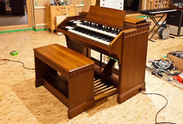
6.1 Safety first: the death cap & B+
6.1.1 The AC “death cap”
Older Hammond consoles (B-3/C-3 and predecessors) and Leslie cabinets were manufactured when a two-wire, non-polarised mains plug was standard. Many units left the factory with a small capacitor wired from one leg of the AC line directly to the chassis — the so-called “death cap” — originally intended for RF interference and hum suppression. Typical values are 0.047 µF to 0.1 µF, paper, wax, or early film construction (HammondWiki, “Death Caps,” dairiki.org; KR Sound, kr-sound.com).
The hazard is in the failure mode. These period components fail short, not open, and “then you have Mains AC directly connected to chassis” — placing full line voltage (120 V RMS at 60 Hz in North America; 230 V RMS at 50 Hz in many export markets) on every exposed metal surface of the instrument: the keybed rail, pedal hardware, expression-pedal frame, Leslie chassis, and cabinet hardware (dairiki.org, quoting the failure mode; KR Sound, kr-sound.com).
The restoration fix is unambiguous and must be completed before the instrument is returned to service.
Tools required: soldering iron (25 W to 60 W, temperature-controlled), solder sucker or desoldering braid, diagonal cutters, 3-conductor grounded mains cord (NEMA 5-15P or IEC 320-C13 as applicable; minimum 18 AWG / 0.75 mm², 6 ft / 1.8 m), heat-shrink tubing (1/4 in / 6.4 mm), digital multimeter (DMM, 600 V AC range), insulated gloves (1 000 V-rated).
- Locate the death cap. On the B-3/C-3 console it is typically found at the mains terminal block or power-supply chassis, a small axial capacitor bridging one AC leg to the chassis ground lug. On the Leslie 122 it is at the amplifier chassis near the mains input. Consult the unit’s own schematic to confirm the exact location before touching anything (Hammond B-3/C-3 Service Manual; dairiki.org, “Death Caps”).
- Unplug the instrument completely before any work. Verify zero AC voltage at the terminal block with the DMM (600 V AC range) — confirm 0 V before touching any internal component.
- Remove the death cap entirely. Unsolder or clip both leads, withdraw the component from the chassis, and cap the vacated solder pads with heat-shrink. Do not replace it with another non-safety-rated part.
- Install a grounded three-conductor (earthed) mains cord. Bond the chassis ground lug to the mains earth (safety ground) conductor so that any future fault trips the branch-circuit breaker rather than energising the chassis (dairiki.org; KR Sound, kr-sound.com).
- Locate the hum-buck / polarity switch (if fitted). With the grounded cord installed, this switch is vestigial — the chassis is now clamped to true ground. Disconnect its leads from the terminal block and either remove the switch or leave it in its panel hole with the leads individually insulated (heat-shrink); do not leave it wired into the restored circuit. (captain-foldback.com)
- Verify the earth bond. With the cord installed and the instrument unplugged, measure continuity (< 1 Ω) from the chassis ground lug to the earth pin of the new mains plug. A reading above 1 Ω indicates a connection fault; correct before use. Also verify the mains outlet’s own safety ground is functional with a receptacle/plug tester before returning the instrument to service — a grounded cord in an ungrounded outlet provides no protection.
- Optional RF suppression only: if a line-to-chassis capacitor is genuinely needed after the earth is in place, fit only a Y2-class safety capacitor (rated to IEC 60384-14 or equivalent; 0.047 µF to 0.1 µF, 250 V AC rated). A Y2 cap is constructed to fail open, not short, so a failure cannot reconnect the line to the chassis (dairiki.org; KR Sound). A standard film or electrolytic cap is never acceptable in this position.
Warn: The death cap is a direct electrocution hazard. On any pre-grounded-cord Hammond console or Leslie cabinet, remove the line-to-chassis death cap and install a grounded three-wire cord before the instrument is used or serviced. A failed death cap can put full mains voltage (120 V RMS at 60 Hz, or 230 V RMS at 50 Hz) on the keybed, pedal contacts, and Leslie chassis simultaneously. Never replace it with a standard film cap; only a Y2-rated safety capacitor may occupy a line-to-chassis position, and only alongside a proper mains earth (dairiki.org; KR Sound, kr-sound.com).
Death-cap removal and 3-wire ground conversion — before and after:
6.1.2 B+ high voltage after power-off
The AO-28 preamplifier carries a B+ rail of approximately +200 VDC (at the V-7 pin 1 reference node; bentonelectronics.com, “Servicing the Hammond B-3 Type Pre-Amp”; Vol 08 §“Power supply & safe discharge”). The Leslie 122 power amplifier carries approximately +415 VDC at the 6550A output plates (bentonelectronics.com, “Servicing the Leslie 122 Amplifier”; Vol 04 §4 “The amplifier & power supply”). Both voltages are stored on large electrolytic filter capacitors and do not immediately drain when the equipment is switched off or unplugged.
Warn: Switching off or unplugging the organ and the Leslie does not make the high-voltage sections safe to touch. The B+ stored on the filter capacitors is lethal — a current above approximately 10 mA through the chest cavity is potentially fatal, and +400 V can drive that current through normal skin resistance. Assume every filter capacitor is fully charged until a meter reads otherwise. Discharge and verify before any soldering, component removal, or hand contact with the high-voltage sections (bentonelectronics.com; general tube-amp safety practice).
Capacitor-discharge procedure (required before all chassis work on the AO-28, the console power supply, and the Leslie 122 amplifier):
Tools required: digital multimeter (DMM) set to 600 V DC range (or 1 000 V range if available), discharge resistor tool (10 kΩ to 25 kΩ wirewound, 10 W minimum — for +430 V across 10 kΩ the dissipation is V²/R = 430² / 10 000 = 18.5 W, so use a ≥ 25 W unit or two 10 W units in series), insulated clip leads (1 000 V rated), insulated gloves (1 000 V rated).
- Power off the console (both START and RUN switches off) and the Leslie 122. Pull both mains plugs.
- Wait a minimum of 5 minutes — but do not assume time alone is sufficient; some capacitors bleed through internal leakage, others do not bleed at all.
- Set the DMM to DC volts, 600 V range. Measure across the main B+ filter capacitor terminals (consult the unit schematic for the exact test points). Note the reading. Expect up to +430 VDC on an unbled Leslie supply; the console power-supply caps typically drain faster through the tube heater load, but verify regardless.
- If voltage is present: connect the discharge resistor across the capacitor terminals using insulated clip leads. Keep one hand behind the back; never contact both leads or both terminals simultaneously.
- Monitor the DMM as the voltage falls. Time constants for reference: for a 100 µF cap through 10 kΩ, τ = RC = 10 000 × 100 × 10⁻⁶ = 1.0 s — five time constants (5 s) brings the voltage below 1 % of initial (e⁻⁵ ≈ 0.67 %, i.e. ≈ 2.9 V at 430 V initial). For a 500 µF cap through the same resistor: τ = 5 s, so allow at least 25 s. In all cases, wait for the DMM to confirm below 5 VDC before proceeding.
- Re-measure at every section of a multi-section filter capacitor. A section whose path did not include the resistor can remain charged.
- Keep one hand clear of the chassis throughout. Re-verify after any pause; filter capacitors can recover a partial surface charge (“dielectric soak”) after an initial discharge.
Warn: Never discharge an HV filter capacitor by shorting it with a bare screwdriver or bare jumper wire. A dead short can vaporise the conductor, spray molten metal, and damage the capacitor and surrounding components. Use only a resistor-limited discharge tool (10 kΩ to 25 kΩ, ≥ 10 W), then verify below 5 VDC with the meter at every capacitor section before touching the circuit (bentonelectronics.com; general tube-amp safety practice).
6.2 Moving & lifting a console
6.2.1 Weights
The B-3 console body on its leg set weighs approximately 310 lb (140 kg) (est.); adding the 25-note bass pedalboard brings the fully assembled instrument to approximately 425 lb (193 kg) (est.) — the figure commonly cited in service discussions (organforum.com; HammondWiki). The Leslie 122 cabinet weighs approximately 150 lb (68 kg) (est. — trade consensus; consistent with amplifiedparts.com service notes). Both figures are for stock configurations; field units with modified cabinetry, added hardware, or custom wiring may vary.
The two heaviest sub-assemblies inside the console are the tonewheel generator and the manual frames (upper and lower keyboard frames with bus wiring). The generator alone is estimated at approximately 45 lb (20 kg) (est.; dairiki.org/HammondWiki, “WhatDoesAHammondWeigh”; organforum.com service discussions) — a separate teardown target when the console must be moved through a doorway narrower than the assembled cabinet.
6.2.2 Procedure — moving a B-3 console
Equipment: two persons minimum; four furniture dollies rated ≥ 300 lb (136 kg) capacity each, locking casters preferred; moving straps or appliance hand-truck; packing blankets.
- Remove the organist’s bench from under the console. The bench stores under the rear of the instrument; set it aside.
- Disconnect all external cabling — the 6-pin Leslie cable, any MIDI or audio extensions, and the mains cord. Coil and label each cable.
- With person one steadying the console, person two places a dolly under one front leg. Tilt the console slightly toward person one while person two places the second dolly under the rear leg on the same side. Lower the console onto both dollies. Repeat on the opposite side. Confirm all four legs are supported.
- Lock the dolly casters (if locking type) before releasing hand support. Otherwise have person two maintain contact while person one steers.
- Roll the console slowly over level, obstacle-free floor. Move at walking pace; the instrument is top-heavy and will tip if accelerated or steered sharply.
- Over a threshold or ramp: tilt the console rearward slightly and guide the front dollies over the obstruction under controlled load — never allow the console to roll freely down a slope. Two people required throughout.
- To load into a vehicle: use a rated furniture ramp with moving straps, two people on the low side controlling descent or assisting upward push. Do not push from the manual end.
Warn: Never lift the Hammond B-3 console by the manual assemblies (keyboard frames), the drawbar rail, or the top panel. These are not structural members and will crack, distort, or separate from the console frame under the instrument’s full weight. Lift only from the solid wood sides or the underframe rails (organforum.com; general restoration practice). Two people are required; the console must not be moved solo.
6.2.3 Procedure — moving a Leslie 122 cabinet
Equipment: two persons minimum; two furniture dollies or a rated appliance hand-truck; moving strap.
- Power down and unplug the Leslie. Disconnect the 6-pin cable from the back.
- Fit dollies under the two base corners of the cabinet, or engage the hand-truck under the base. The Leslie 122 cabinet is front-heavy (the amplifier, crossover, and transformer are at the front bottom).
- Keep the cabinet upright at all times. Person one stabilises the top; person two steers the base. Roll slowly.
- Two people: hands on the cabinet sides — not on the grille cloth — throughout the move.
Warn: Do not lay the Leslie 122 on its side or back in transit. The rotor spindles and their thrust bearings are not designed for non-vertical loading; a tipped cabinet can displace the horn-motor shaft, damage the upper-rotor bearing, or allow the bass-drum assembly to shift against the enclosure walls (trade practice; organforum.com). If a doorway requires minimal tilting, tilt only forward (horn side up) and minimally.
6.3 The refurb toolkit
The following table lists the tools needed across the Part II volumes. The specific tools required for each procedure are called out at the head of that procedure’s step list; the table here is the stocking reference.
Table 1 — The refurb toolkit
| Tool | Specification / notes | Used in |
|---|---|---|
| Digital multimeter (DMM) | 600 V DC / 600 V AC ranges minimum; true-RMS preferred; CAT III-rated for mains work (e.g. Fluke 115, Fluke 87V, or equivalent) | All voltage, continuity, and resistance checks |
| AC voltmeter or DMM AC range | For mains voltage verification at terminal blocks; CAT III | Death-cap check, variac ramp |
| ESR meter | Measures equivalent series resistance of electrolytics — low ESR = healthy dielectric; high ESR = dried out (e.g. PEAK ESR70, Atlas ESR+, or equivalent) | Vol 08 recap; Vol 11 Leslie cap check |
| Capacitance meter / DMM cap function | µF range; for verifying cap values against the schematic | Vol 08, Vol 11 |
| Variac (variable autotransformer) | 0–140 V AC output, ≥ 280 VA; dial calibrated in volts or percentage of mains | §“Powering up a long-stored instrument” |
| Isolation transformer | 120 V : 120 V (1:1), ≥ 500 VA; breaks the direct mains-to-chassis path for hot-chassis diagnosis; not a substitute for the death-cap fix | §“Powering up”; hot-chassis diagnosis |
| Discharge resistor tool | 10 kΩ–25 kΩ wirewound, ≥ 25 W (see §‘B+ high voltage’ for sizing math), fitted with insulated clip leads; drains filter caps before hand contact | All HV chassis work |
| Soldering iron | Temperature-controlled, 25 W to 60 W; fine conical tip for circuit board work; chisel tip for grounding lug connections (e.g. Hakko FX-888D or equivalent) | Death-cap fix; Vol 08; Vol 11 |
| Desoldering tool | Solder sucker or fine desoldering braid; for removing the death cap and old capacitor leads | Death-cap fix; Vol 08 recap |
| Nut drivers | 1/4 in (6.4 mm) hex and 5/16 in (7.9 mm) hex, stubby preferred for chassis access inside the console | Generator removal; Vol 07; Vol 09 |
| Screwdrivers — flat | 1/8 in (3.2 mm), 3/16 in (4.8 mm), 1/4 in (6.4 mm); long-reach 6 in (150 mm) blade for reaching inside the lower console | General chassis work |
| Screwdrivers — Phillips | #1 and #2 | General chassis work |
| Long-nose pliers | Standard and 90° bend; for routing leads inside the console frame | General internal work |
| Diagonal cutters | Flush-cut style; for trimming capacitor leads and removing the death cap | Death-cap fix; Vol 08 recap |
| Contact cleaner — DeoxIT D5 or D100 | Residue-free, safe for precious-metal contacts and most plastics (Caig Laboratories; organforum.com). Apply only to key contacts, drawbar contacts, and relay contacts. Do not spray into the vibrato scanner — see Warn below and Vol 10 | Vol 09 contacts; Vol 11 relay |
| Tube tester | Calibrated for 6550A/KT88, 12AU7A, 12AX7; useful for auditing an existing tube complement before committing to a full retube | Vol 11 Leslie retube |
| 6-pin Leslie test lead | A short breakout cable terminated in an Amphenol 6-pin connector on one end and individual insulated test leads or a breakout jack on the other; for signal-tracing the console-to-Leslie interface without live mating/de-mating | §“Diagnostic first principles”; Vol 11 |
| Insulated alligator clip leads | Short (6 in / 150 mm) and long (24 in / 610 mm); for signal injection and temporary bridging during diagnosis | Diagnostics throughout |
| LED work light or flashlight | Gooseneck or panel; the inside of the B-3 console is deeply shadowed | All internal work |
| Inspection mirror | Small angled mirror on an extension rod; for reading capacitor markings in deep chassis recesses | Vol 08; Vol 11 |
| Anti-static wrist strap | Not critical on the B-3 (no CMOS devices) but good practice for the line-box and AO-28 circuit boards | Vol 08; Vol 10 |
Warn: DeoxIT contact cleaner must not be sprayed into the vibrato scanner. The scanner rotor sweeps across 16 fixed capacitor plates separated by narrow air gaps and fibre insulators; solvent or lubricant residue on those plates alters the dielectric and changes the vibrato character, and a conductive residue can short the capacitor sections to ground. Scanner cleaning is a dry procedure detailed in Vol 10 §“Scanner plate cleaning” (bentonelectronics.com, “Servicing the Hammond Vibrato Scanner”).
6.4 Consumables
The following consumables should be stocked before beginning any Part II service work. Quantities below are for a single console plus a single Leslie 122.
Warn: Do not substitute 3-in-1 oil, household mineral oil, or automotive motor oil for Hammond tonewheel-generator oil in the console generator. Wrong- viscosity or detergent-containing oils gum the cotton wicking threads; once gummed, the affected threads must be replaced to restore lubrication to the bearings they serve. Use only Hammond-branded tonewheel-generator oil in the console; the Leslie motor felt pads have a more tolerant specification (bentonelectronics.com; Vol 07 §“Why only Hammond oil”).
Table 2 — Consumables
| Consumable | Specification | Quantity (one console + one Leslie 122) | Source |
|---|---|---|---|
| Hammond tonewheel-generator oil | Low-viscosity, non-detergent mineral oil; Hammond OG-1 or current equivalent | 2 fl oz (60 mL) minimum | hammondorganco.com/oils; tonewheelgeneral.com |
| Leslie oil or non-detergent machine oil | Light non-detergent oil for Leslie motor felt-pad reservoirs; sewing-machine oil is the accepted substitute for Leslie motor bearings only (bentonelectronics.com) | 1 fl oz (30 mL) | Leslie service parts; pharmacy sewing-machine oil |
| Solder | 63/37 or 60/40 Sn/Pb rosin-core; 0.032 in (0.8 mm) dia. for circuit-board joints; 0.062 in (1.6 mm) for heavier grounding connections | 1 oz (28 g) per diameter | Electronics suppliers |
| Desoldering braid | Fine (#2) and medium (#4); cut a fresh length for each use to avoid contaminating the work | 5 ft (1.5 m) per width | Electronics suppliers |
| Heat-shrink tubing | 1/8 in (3.2 mm) and 1/4 in (6.4 mm) dia., polyolefin, 2:1 shrink ratio; for insulating splices and capping vacated solder pads | Assorted pack | Electronics suppliers |
| DeoxIT D5 or D100 spray | Residue-free contact cleaner; see scanner Warn above | 1 can | caig.com; electronics distributors |
| Grounded 3-wire mains cord | NEMA 5-15P for North American units; IEC 320-C13 or hardwired to terminal block depending on console variant; ≥ 18 AWG (0.75 mm²) three-conductor, ≥ 6 ft (1.8 m) | 1 per unit being retrofitted | Hardware or electrical suppliers |
| Y2-class safety capacitor (optional) | IEC 60384-14 Y2 rated; 0.047 µF to 0.1 µF, 250 V AC working; for RF suppression only alongside the new earth — see §“The AC death cap” | 1 per unit (if used) | Electronics suppliers (Vishay, Kemet, or Murata Y2 series) |
| Electrolytic capacitors (recap kits) | Values are chassis-revision-specific; read from part markings or the unit’s own schematic — part lists are in Vol 08 (AO-28 and console power supply) and Vol 11 (Leslie 122) | Per Vol 08 / Vol 11 kit lists | Benton Electronics; restoration trade kits |
| Leslie drive belts | Upper horn drive: ≈ 25.5 in (648 mm) circumference, rubber; lower drum drive: ≈ 31 in (787 mm), polyurethane (amplifiedparts.com; tonewheelgeneral.com) | 1 set (2 belts) per Leslie | amplifiedparts.com; tonewheelgeneral.com |
| Isopropyl alcohol (IPA) | ≥ 90 % purity; for cleaning flux residue after soldering and for cleaning busbar surfaces (Vol 09) | 4 fl oz (120 mL) | Pharmacy or electronics supplier |
6.5 Powering up a long-stored instrument
6.5.1 Why a variac ramp is essential
An electrolytic capacitor that has been unpowered for months or years develops partial breakdown of its aluminium-oxide dielectric. Applying full mains voltage directly to an unserviced, long-stored console or Leslie slams the filter capacitors with full B+ cold, which can puncture the dielectric, vent or rupture the capacitor, and damage the tube rectifier or solid-state supply diodes in a single power-on event (captain-foldback.com, “Safe B3 Power-Up and Death Cap Removal”; bentonelectronics.com, “Servicing the Leslie 122 Amplifier”).
The standard mitigation is to slowly ramp the mains voltage via a variac, allowing the capacitor dielectric to reform gradually under controlled current. This is the industry-standard first move for any long-dormant tube amplifier or console (captain-foldback.com; tube-amp service practice generally).
6.5.2 Equipment setup — the ramp rig
Tools and equipment: variac (0–140 V AC, ≥ 280 VA); isolation transformer (1:1, ≥ 500 VA); DMM (AC volts range + DC volts range); discharge resistor tool; fused extension lead rated for the console’s normal mains current (typically ≤ 3 A at 120 V for the console alone).
Wiring the ramp rig:
6.5.3 The variac ramp procedure
Prerequisites: death cap removed; grounded three-wire cord fitted and earth-bond verified (< 1 Ω chassis-lug to earth pin); discharge resistor tool and DMM on hand at the bench throughout.
- Set the variac output to 0 V (dial fully counter-clockwise). Connect the isolation transformer primary to the wall outlet; connect the isolation transformer secondary to the variac input; connect the variac output to the instrument’s new grounded mains cord.
- Turn on the instrument’s own switches — both START and RUN on the console; power switch on the Leslie. Because the variac delivers no voltage yet, nothing runs. This ensures the instrument’s internal switching is not in series with the ramp.
- Advance the variac to 25 V AC (approximately 20 % of rated mains). Hold for 10 minutes. Observe: no arcing, no smoke, no burning smell, no audible discharge.
- Advance to 50 V AC (≈ 40 % of mains). Hold 10 minutes.
- Advance to 75 V AC (≈ 60 %). Hold 10 minutes. The console start motor may begin to tick; the Leslie motor may begin to stir at this voltage — expected behaviour.
- Advance to 100 V AC (≈ 80 %). Hold 10 minutes. Monitor the DMM across the main filter capacitor (B+ rail); the voltage should be rising proportionally, not yet at full B+.
- Advance to 120 V AC (full rated mains). Hold 15 to 30 minutes. The console should now start and run normally. The Leslie 122 B+ target under idle conditions is approximately +415 VDC at the 6550A plates (bentonelectronics.com; Vol 04 §4 “The amplifier & power supply”). Confirm no audible hum above normal, no arcing, and no burning odour.
- If the instrument passes the 120 V hold: power down via its own switches. Wait 5 minutes, then discharge and verify all filter caps per §“Capacitor-discharge procedure” above. Proceed to electrical inspection or the next service step.
Warn: If a capacitor vents (a pop, hiss, or electrolyte odour), if current draw rises sharply (add a series current clamp or series ammeter if available), or if any burning odour is detected at any step: immediately set the variac to 0 V and power down. Do not advance further. A venting or failing capacitor must be replaced (Vol 08 for the AO-28 and console power supply; Vol 11 for the Leslie 122) before the instrument is run at full mains (captain-foldback.com; bentonelectronics.com).
Note: The isolation transformer breaks the direct mains-to-chassis path, which enables hot-chassis troubleshooting without mains-referenced shock exposure from a chassis-ground fault. It is not a substitute for removing the death cap — the death-cap fix is permanent; the isolation transformer is a bench diagnostic aid only (captain-foldback.com, “Safe B3 Power-Up and Death Cap Removal”).
6.6 Diagnostic first principles
6.6.1 The start/run sequence
Before any signal tracing, confirming that the organ starts and runs correctly is the mandatory first diagnostic step. An organ that does not run correctly cannot yield meaningful signal-level data.
Normal start sequence:
- START switch ON: the shaded-pole induction start motor drives the generator shaft up to speed through its sliding pinion gear. A mechanical clunk or click as the pinion engages is normal (Hammond B-3/C-3 Service Manual). The generator accelerates toward synchronous speed.
- RUN switch ON (after the start motor has had a few seconds): the synchronous run motor locks to the mains frequency and takes over drive; the start motor’s pinion retracts. Run-up to full synchronous lock takes approximately 20 s to 30 s from cold (bentonelectronics.com, “Hammond Synchronous Run Motor”). Pitch is stable when synchronous lock is achieved — approximately 1 200 rpm on 60 Hz mains (Vol 02 §2.1 “The synchronous motor”).
- Sound is available from the manuals into the Leslie once the run motor is locked. The Leslie’s own speed-changeover relay responds to the half-moon switch command from the console independently of the console start/run sequence.
Warn: Do not leave the console on START only for extended periods. The start motor is a shaded-pole induction motor rated only to bring the generator to speed; running it continuously generates excess heat and will damage the motor windings and the sliding pinion assembly (organforum.com; bentonelectronics.com, “Hammond Generator Start Motor”).
6.6.2 Fault triage
The table below maps the three primary failure presentations to their most probable causes and the diagnostic chain for each. This is a first-pass triage guide; the full repair procedure for each cause is in the referenced volume.
Table 3 — Fault triage
| Symptom | First check | Probable cause | Refer to |
|---|---|---|---|
| No start — motor does not turn | Mains present at terminal block (DMM, AC volts)? START switch continuity? | Open mains cord; failed START switch; open start-motor winding; seized generator shaft | Vol 02 §2.1; Vol 07 §“Generator seizure” |
| Starts but no run lock — generator turns but speed drifts | Mains frequency nominal? Run-motor winding continuity (target ≈ 90 Ω at the parallel-wired terminals; each individual coil ≈ 180 Ω)? | Failed run-motor winding (one or both coils open); generator partially seized | Vol 02 §2.1 |
| Runs but no sound from manuals | AO-28 B+ present? AO-28 output signal at 6-pin connector? | Failed key contacts (open harmonic); open AO-28 tube; failed matching transformer; open or corroded 6-pin cable | §“Safety first” (death cap); Vol 09 contacts; Vol 08 AO-28 |
| Runs but no Leslie output | 6-pin cable continuity? Leslie amp B+ present? Fuse intact? | Open or corroded 6-pin connector; failed Leslie amp (open tube, blown fuse, failed filter cap); stuck speed-changeover relay | Vol 11 §“Amplifier”; Vol 11 §“Connectors & relay” |
| Leslie won’t spin (amp works) | Rotor shaft free to turn by hand (power off, cap discharged)? Belt present and not broken? Motor winding continuity? | Broken or perished drive belt; seized rotor shaft bearing; failed rotor motor winding | Vol 11 §“Belts”; Vol 11 §“Motors” |
| Intermittent or weak individual notes | Which harmonic (which drawbar)? One drawbar affects all notes or just one key? | Oxidised key contact (one harmonic = one defective contact per key); dirty busbar | Vol 09 §“Key contacts”; Vol 09 §“The Hammond fix” |
| Mains hum — 60 Hz or 120 Hz | Is the hum from the console or the Leslie (disconnect and test each independently)? | Dried or high-ESR filter caps in the console power supply; dried filter caps in the Leslie 122 amp | Vol 08 §“Power-supply recap”; Vol 11 §“Recap” |
| Vibrato weak or erratic | Oil visible on scanner plates (inspect with flashlight through the motor/scanner cover)? Line box previously rebuilt? | Oil contamination on scanner plates; drifted line-box components | Vol 10 §“Scanner cleaning”; Vol 10 §“Line box” |
6.6.3 Signal-tracing the generator → preamp → Leslie chain
When the fault presentation is “runs but no sound” or “intermittent sound,” the signal path is traced from source to output to isolate the failing stage.
Tools: DMM (AC mV range) or audio-frequency signal tracer, audio probe (a 0.1 µF to 1 µF capacitor in series with a high-impedance earphone), insulated alligator clip leads, 6-pin Leslie test lead.
- Confirm generator output. With the organ running at 120 V AC mains (via the variac if still ramping), hold a key down with a drawbar pulled and measure AC voltage across the corresponding footage busbar terminals (consult the schematic for bus locations). Expect a signal on the order of a few hundred mV RMS, varying by footage and drawbar position (Vol 02 §2.3 “The key-contact matrix”). Silence here: generator output or key-contact fault.
- Confirm AO-28 input. Trace the signal forward from the drawbar matching transformer output into the AO-28 input jack. The AO-28 is a tube preamplifier (Vol 02 §2.5 “The AO-28 preamp and matching transformer”); signal present at input but absent at output indicates a failed AO-28 tube or open coupling capacitor.
- Confirm AO-28 output at the 6-pin connector. Using the 6-pin Leslie test lead, verify audio signal on the balanced-audio pin pair (pins 1 and 2 on the Amphenol 6-pin, per the Hammond B-3/C-3 Service Manual). Signal present here but absent from the Leslie: the Leslie amp or cable is the fault (Vol 11).
- Confirm Leslie amp output at the speaker terminals. With the 6-pin cable connected and the Leslie running, probe the output-transformer secondary for AC audio when a key is held on the organ. No signal here: Leslie amp fault (Vol 11 §“Amplifier”).
Note: Signal injection — introducing a known test tone at a defined injection point using a signal generator — can isolate a fault to one side of a stage boundary when passive probing yields ambiguous results. Inject at the AO-28 input to confirm the console output chain independently of the Leslie; inject at pin 1/2 of the 6-pin via the test lead to confirm the Leslie in isolation. Keep injected signal levels low (on the order of 100 mV RMS) to avoid overdriving tube stages.
Sources: Hammond B-3/C-3 Service Manual (period document; schematic test points, terminal-block layout, motor specifications); captain-foldback.com (Trevor Cousins, “Safe B3 Power-Up and Death Cap Removal” — variac ramp procedure and isolation transformer rationale; primary source for §“Powering up”); bentonelectronics.com, “Servicing the Leslie 122 Amplifier,” “Hammond Synchronous Run Motor,” and “Hammond Generator Start Motor” (B+ voltages; motor winding resistance targets; reform/ramp procedure; consumable specifications); dairiki.org / HammondWiki, “Death Caps” (death cap failure mode, Y2 safety-capacitor recommendation); KR Sound, kr-sound.com (death cap construction, failure mode, correct fix); organforum.com (console weight estimates ≈ 425 lb / 193 kg; service discussion on generator weight; lifting practice); goffprof.com (general B-3 service reference; consumables); amplifiedparts.com (Leslie 122 belt specifications: upper ≈ 25.5 in / 648 mm, lower ≈ 31 in / 787 mm); tonewheelgeneral.com (belt and oil specifications); caig.com (DeoxIT D5/D100 contact cleaner; scanner-contamination note). Console weight ≈ 425 lb (193 kg) and Leslie 122 weight ≈ 150 lb (68 kg) are trade-consensus estimates marked (est.); no manufacturer weight specification was located in the consulted period documentation. Cross-references: Vol 02 §2.1 (synchronous motor and start/run sequence), Vol 02 §2.3 (key-contact matrix and busbar signal), Vol 02 §2.5 (AO-28 preamp), Vol 04 §4 (Leslie 122 amplifier and B+ rails), Vol 07 (tonewheel generator oiling and service), Vol 08 (AO-28 recapping and console power-supply recap), Vol 09 (key contacts, the Hammond fix, and drawbar contacts), Vol 10 (vibrato scanner cleaning and line-box rebuild), Vol 11 (Leslie 122 service: amp, belts, motors, connectors), Vol 12 (standard-cabinet restoration).
Comments (0)