Hammond B-3 · Volume 4
Hammond B-3 — Vol 04: The Leslie 122
This volume documents the Leslie Model 122 — the rotating-speaker cabinet that is the canonical acoustic partner to the Hammond B-3. It covers why a rotating loudspeaker produces the signature swirl (Doppler frequency modulation, amplitude modulation, and comb filtering), the cabinet’s mechanical and electrical anatomy, its ~40 W tube power amplifier and high-voltage supply, the passive 800 Hz crossover, the two independent rotors, the two-speed (tremolo/chorale) motor system with its half-moon switch, and the balanced 6-pin connection that distinguishes the 122 from its unbalanced 6-pin sibling, the 147 (both use a 6-pin connector — the difference is balanced “6H” wiring vs unbalanced “6W” wiring, not the pin count). The B-3 console, its AO-28 output amplifier, and the scanner vibrato/chorus upstream of the cabinet are Vol 02 §2.x and Vol 03 §3.x; mic’ing the rotating field is Vol 17 §17.x and Leslie service is Vol 11 §11.x — both are referenced here, not duplicated.
Note: The Leslie effect sits acoustically downstream of everything in Vols 02–03. The scanner chorus/vibrato (Vol 03 §3.4) is an electronic modulation applied to the signal before it leaves the console; the Leslie rotation is a mechanical, acoustic modulation applied to the sound in the room. The two stack independently, which is why players treat them as separate colours.
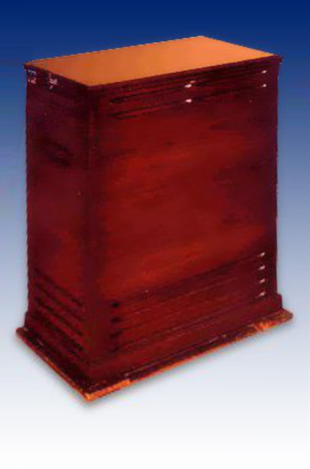
4.1 Why a rotating speaker
A stationary loudspeaker radiates a fixed sound field: the listener hears one direct path plus the room’s reflections, unchanging in time. Donald Leslie’s insight was to put the radiating element in motion so that the sound field itself sweeps continuously. The perceived effect is not a single phenomenon but the superposition of three, all driven by the same rotation:
- Doppler frequency modulation. As the mouth of a rotating horn swings toward the listener, the wavefronts are compressed and the pitch rises slightly; as it swings away, the wavefronts stretch and the pitch falls. Over one revolution the source velocity varies sinusoidally, so the radiated tone is frequency-modulated, producing a sequence of FM sidebands around every partial in the signal (Leslie speaker, en.wikipedia.org; theatreorgans.com Hammond-Leslie FAQ). At tremolo speed (~400 rpm, ≈ 41.9 rad/s) with the horn tip at an approximate radius of ~90 mm (≈ 3.5 in) (est. from service photos), the peak tip velocity is approximately 3.8 m/s against a speed of sound of ~343 m/s at 20 °C — a Doppler-shift ratio of roughly ±1.1 %, or approximately ±19 cents on any partial (est.; sensitive to actual tip radius and room temperature). This is wide enough to be plainly audible as pitch vibrato, and markedly broader than the console’s scanner vibrato (Vol 03 §3.4) at ±7 Hz (a few cents at typical playing pitch). This is the core of the “vibrato-like” pitch movement.
- Amplitude modulation (tremolo). A horn is directional — it beams its energy. As the mouth rotates past the listener, the on-axis lobe sweeps across them, so the level at the listening position rises and falls once per revolution. The same rotation therefore also imposes a tremolo, in phase-locked relation to the pitch sweep (en.wikipedia.org). The name “tremolo” for the fast speed comes from this amplitude component.
- Comb filtering and room interaction. The moving source continuously changes the path-length difference between the direct sound and the wall/floor reflections, so the interference notches (a comb filter) slide up and down the spectrum as the rotor turns. Layered over the FM and AM, this gives the effect its shimmering, three-dimensional “chorusing” richness rather than a clean single-rate vibrato.
Note (terminology): Despite the “tremolo” label for the fast setting, the dominant pitch modulation of the rotating horn is technically frequency modulation (FM) — “vibrato” in classical terms. The level rise-and-fall is technically tremolo (amplitude modulation), and both happen simultaneously from the same rotation. Hammond and Leslie literature uses “tremolo” for the fast speed because the strong amplitude sweep was what first caught listeners’ attention; the pitch component was secondary in 1940s nomenclature.
The 122 doubles the richness by using two independent rotating sources crossed over at 800 Hz: a treble horn carries the highs (where Doppler and beaming are strong and audible) and a separate bass drum/rotor carries the lows. Because the horn and the drum spin at different rates and are not phase-locked to each other (see §“Horn & drum rotors”), the high-frequency swirl and the low-frequency wash drift in and out of alignment, producing a complex, evolving field that a single rotor — or any electronic emulation of one — struggles to match.
Tip: The most dramatic part of the sound is the inertia ramp at a speed change. The rotors are heavy and belt-driven, so switching tremolo→chorale (or back) does not snap between speeds — the horn and drum spin down or up over a second or more, and because they have different masses they ramp at different rates, smearing the pitch and tremolo through a sweep that is itself a signature gesture (Vol 03 §3.x covers the half-moon switch as a control; the mechanical ramp is detailed in §“Chorale vs tremolo” below).
4.2 Anatomy of the 122
The 122 is a tall floor cabinet — 41 in (1,041 mm) high (en.wikipedia.org), with a footprint of approximately 19 in × 23 in (483 mm × 584 mm) (est. from period service photographs) — that partitions, top to bottom, into the upper treble-horn compartment, the lower bass-rotor compartment, and the amplifier chassis at the base. Sound and signal flow through it as follows:
- Balanced input arrives on the 6-pin connector from the Hammond’s AO-28 output amplifier (§“The 6-pin balanced interface & speed signalling”).
- The signal is amplified by the ~40 W push-pull tube power amplifier (§“The 40 W amplifier”).
- The amplifier output feeds a passive 800 Hz crossover that splits the band (§“Crossover & drivers”).
- Highs (above 800 Hz) drive a Jensen 3/4-inch (19 mm) throat compression driver (theatreorgans.com Hammond-Leslie FAQ) that fires through a rotating twin-bell Bakelite horn casting — one bell radiates, the other is a sealed dummy acting as an aerodynamic and mass counterweight.
- Lows (below 800 Hz) drive a downward-firing 15-inch (381 mm) woofer whose output is redirected sideways by a rotating bass drum/rotor baffle.
- Two motors per rotor (a fast and a slow motor) spin the assemblies via belts; the half-moon switch on the organ selects the speed, with the switching information carried back over the same 6-pin cable (§“Chorale vs tremolo & the half-moon switch”).
Note: “Drum” and “rotor” refer to the same lower element: the woofer itself does not rotate. It fires into a rotating drum-shaped baffle (open on one side) that scoops and slings the low-frequency energy around the cabinet, producing the bass Doppler/AM. Likewise only the horn casting rotates up top, not the compression driver, which is stationary on the rotor axis and couples to the horn through the hollow rotating shaft.
4.3 The 40 W amplifier
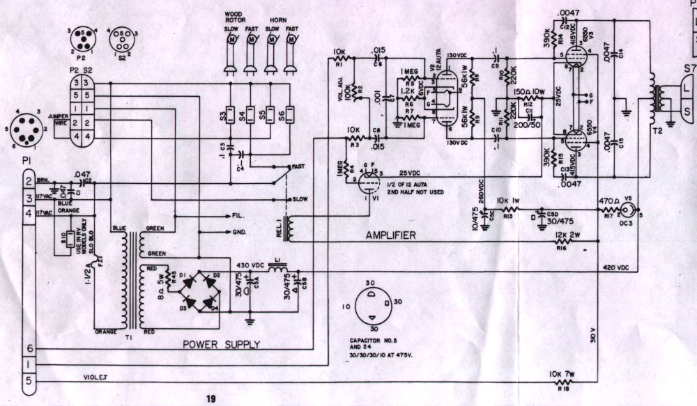
The 122 carries a single-channel vacuum-tube power amplifier rated at roughly 40 W output (en.wikipedia.org; bentonelectronics.com, “Servicing the Leslie 122 Amplifier”). It is deliberately modest in headroom — a hard-driven B-3 will push it into the warm tube overdrive that is part of the classic sound. The tube complement, as documented in the 122/142 amplifier service literature, is:
Table 1 — The 122 carries a single-channel vacuum-tube power amplifier rated at roughly 40 W output (en.wikipedia.org; bentonelectronics.com, "Servicing the Leslie 122 Amplifier"). It is deliberately modest in headroom — a hard-driven B-3 will push it into the warm tube overdrive that is part of the classic sound. The tube complement, as documented in the 122/142 amplifier service literature, is
| Stage | Tube | Role |
|---|---|---|
| Input / driver / speed switch | one 12AU7A (dual triode) | First triode section: balanced input amplifier and phase splitter (drives the 6550A grid). Second triode section: speed-switching detector — its grid couples via a 1 MΩ resistor to the balanced audio pair and detects the common-mode DC from the console; when ~60 VDC (est.) is present it conducts and energises the chorale relay (bentonelectronics.com; lambertsmusicsolutions.com). The same 12AU7A serves both audio and motor-control functions. |
| Power output | a matched pair of 6550A | Push-pull Class AB output stage delivering ~40 W (bentonelectronics.com) |
| Voltage regulator | one OC3 gas-discharge regulator | Holds the screen/driver supply at a regulated rail (~+310 VDC) by dropping ~105 VDC across the tube (bentonelectronics.com) |
| Rectification | solid-state bridge (four silicon diodes) on the great majority of production units; a rectifier tube on the earliest examples | Produces the main high-voltage B+ from the mains transformer secondary (bentonelectronics.com) |
Note (6AU6): The Leslie 122 amplifier does not use a 6AU6 tube. The complete complement is one 12AU7A, a matched pair of 6550A, and one OC3 — confirmed against the service literature at bentonelectronics.com and the Leslie 122/142 amplifier schematic. No 6AU6 appears in any documented production version of the 122 amplifier.
The supply-voltage nodes, as documented in the Benton service guide (bentonelectronics.com):
Table 2 — The supply-voltage nodes, as documented in the Benton service guide (bentonelectronics.com)
| Node | Nominal voltage |
|---|---|
| Rectifier output (B+ at reservoir capacitors) | ~+430 VDC |
| After main filter choke | ~+420 VDC |
| 6550A plates | ~+415 VDC (est.) |
| OC3-regulated screen / driver rail | ~+310 VDC |
| Preamp section (after 10 kΩ dropping resistor) | ~+260 VDC |
| 12AU7A plates (both triode sections) | ~+130 VDC (est.) |
These are lethal potentials and they persist on the filter capacitors after the cabinet is unplugged.
Warn: The 122 amplifier chassis develops B+ rails of approximately +415 VDC to +430 VDC (bentonelectronics.com). Reservoir and filter capacitors hold a dangerous charge long after power-off and after the cable is pulled. The cabinet must never be opened or serviced live, and the supply must be discharged and verified before any internal work. General bench-safety procedures — mains, grounding, and capacitor-discharge methodology — are in Vol 06 §6.x; Leslie-specific service including 122 amp work, cap-forming and re-capping, and tube bias is Vol 11 §11.x.
Note: Output-tube substitution is a known field variation. The factory 122/142 complement is the 6550A pair (bentonelectronics.com; en.wikipedia.org notes “typically 6550 tubes”), but cabinets in the wild are sometimes found rebiased for other large-bottle pentodes. Any restored unit should be confirmed against its own chassis-stamped revision before assuming the values above; tube-by-tube bias and rail measurement is a Vol 11 §11.x task.
4.4 Crossover & drivers
Between the power amplifier and the two transducers sits a passive crossover with a transition frequency of 800 Hz (en.wikipedia.org; theatreorgans.com Hammond-Leslie FAQ). Everything above 800 Hz is routed to the treble compression driver feeding the rotating horn; everything below 800 Hz is routed to the 15-inch woofer feeding the rotating bass drum. The split is acoustically motivated: 800 Hz sits low enough that the directional, Doppler-rich behaviour of a horn covers the entire range where the swirl is most audible, while the omnidirectional bass is handed to the drum where its slower, broader wash is wanted.
The two transducers matched to this crossover are:
- Treble: Jensen compression driver, 3/4-inch (19 mm) throat diameter. The compression driver is stationary, mounted at the axis of the upper rotor assembly; it fires upward through a hollow rotating shaft into the twin-bell Bakelite horn casting. The conical horn assembly starts vertically above the driver throat and flares horizontally, producing the characteristic sideways radiation. The driver covers the band above 800 Hz, where Doppler FM and directional AM are strongest (theatreorgans.com Hammond-Leslie FAQ).
- Bass: 15-inch (381 mm) dynamic woofer, nominal 16 Ω. Mounted stationary in the lower compartment, firing downward into the rotating drum baffle. The 16 Ω nominal impedance is documented in the service literature (bentonelectronics.com) and differs from typical modern 8 Ω practice; this matters when sourcing a replacement and for output-transformer matching — see Vol 11 §11.x.
The crossover is a passive LC network designed for these specific driver impedances. The crossover is wired for the cabinet’s specific driver impedances; the service literature confirms the 15-inch woofer is a 16 Ω unit (bentonelectronics.com). The exact inductor and capacitor values and the roll-off slope are in the cabinet’s own service data and are not restated as bare numbers here — the 800 Hz transition is the load-bearing figure for understanding the cabinet.
Note: Frequencies near 800 Hz are radiated simultaneously by both rotating sources — the horn’s FM/AM and the drum’s slower wash overlap in the midband, contributing to the dense layered texture there. Any modification to the crossover transition frequency changes both the spectral character of the Doppler swirl and the physical balance between the compression driver’s directional beam and the woofer’s omnidirectional output. Crossover service and component values are in Vol 11 §11.x.
4.5 Horn & drum rotors
The two rotating systems are mechanically and acoustically distinct:
- Treble horn assembly. A stationary Jensen 3/4-inch (19 mm) throat compression driver couples through a hollow rotating shaft into a twin-bell Bakelite casting — the cabinet’s most visually distinctive component. Only one bell (horn) is acoustically open; the second horn is a sealed dummy that exists purely to balance the assembly’s mass and aerodynamics so it spins smoothly and quietly. The casting rotates in the upper compartment while the compression driver sits stationary below it on the rotor axis. The horn assembly covers the band above 800 Hz, where Doppler FM and beam-induced AM are strongest.
- Bass drum/rotor. Below 800 Hz, a downward-firing 15-inch (381 mm) woofer (nominal 16 Ω; bentonelectronics.com) is stationary in the lower compartment and couples into a rotating drum baffle that flings the low-frequency energy around the cabinet. The drum is larger and heavier than the Bakelite horn casting, so it accelerates and decelerates more slowly during speed changes.
Because the two rotors are driven by separate motors and belts at different nominal speeds (next section), their modulations are not synchronized — the high swirl and the low wash continuously drift relative to one another, which is a large part of why the 122 sounds “alive” rather than like a single oscillating source.
4.6 Chorale vs tremolo & the half-moon switch
Each rotor is driven by two AC induction motors — a fast (tremolo) motor and a slow (chorale) motor — coupled to the rotor shaft through rubber belts and idler pulleys. Selecting a speed energises the corresponding motor pair; the rotor’s own inertia then ramps it to the new speed over a second or more, producing the signature accelerating/decelerating sweep.
The speeds documented in the Leslie/Hammond literature are summarised below. Published figures vary slightly between sources and drift with belt wear, line frequency, and motor condition, so the typical values are given with the resulting modulation rate in Hz and flagged where a single authoritative figure could not be pinned:
Table 3 — The speeds documented in the Leslie/Hammond literature are summarised below. Published figures vary slightly between sources and drift with belt wear, line frequency, and motor condition, so the typical values are given with the resulting modulation rate in Hz and flagged where a single authoritative figure could not be pinned
| Rotor | Chorale (slow) | → Hz | Tremolo (fast) | → Hz |
|---|---|---|---|---|
| Treble horn | ~40–50 rpm (est.) | ~0.7–0.8 Hz | ~400 rpm | ~6.7 Hz |
| Bass drum | ~40 rpm (est.) | ~0.67 Hz | ~340 rpm | ~5.7 Hz |
Speeds from en.wikipedia.org (Leslie speaker: chorale horn ~50 / drum ~40 rpm; tremolo horn ~400 / drum ~340 rpm) and corroborating Hammond/Leslie forum and owner’s-manual references (organforum.com; hammondorganco.com owner’s manuals); the chorale figures in particular vary source-to-source and are marked (est.). The horn always runs faster than the drum, and the two are not phase-locked.
Note: The horn’s tremolo rate of ~400 rpm works out to roughly 6.7 Hz, in the same neighbourhood as the console’s scanner vibrato (~7 Hz, Vol 03 §3.4) — which is why the two effects feel related yet distinct: the scanner is a clean electronic ~7 Hz pitch wobble, while the Leslie’s ~6.7 Hz is a spatial sweep carrying AM and comb filtering as well.
Note (inertia ramp): Because the rotors are belt-driven and have substantial rotational inertia, a speed change (tremolo ↔ chorale) does not snap — the horn and drum spin up or down over approximately 5–8 seconds as the rotor inertia ramps up or coasts down (bentonelectronics.com; see Vol 11 §‘Motors, belts & oiling’), and because they have different masses they ramp at different rates. The dual-rate ramp produces a complex, evolving pitch-and-level sweep that is a signature sound in its own right and that no static-speed emulation can fully capture.
Note (50 Hz mains): Installed on a 50 Hz mains supply (European installations), the AC induction motors run at approximately 5/6 of their 60 Hz speed, shifting both tremolo and chorale rates proportionally downward — the tremolo horn drops from ~400 rpm to ~333 rpm (est.), and the resulting modulation rate from ~6.7 Hz to ~5.6 Hz (est.). This broadens the Doppler pitch arc and subtly changes the sound character. Speed adjustment for 50 Hz installations is addressed in Vol 11 §11.x.
The speed is chosen at the organ by the half-moon switch — a semicircular two- (or three-) position lever mounted within reach of the manuals that selects tremolo (fast), chorale (slow), and on many installations an off/brake position. The switch does not carry the audio; it controls the changeover relay inside the 122, and that control information travels back to the cabinet over the same 6-pin cable that carries the audio and AC power (§“The 6-pin balanced interface & speed signalling”). Mic positioning around the rotating field is developed in Vol 17 §17.x.
4.7 The 6-pin balanced interface & speed signalling
The defining electrical distinction of the 122 (and its console-organ sibling the 142) is that it presents a balanced audio input on a 6-pin Hammond connector, and it carries the speed-switching information as a DC voltage applied as a common-mode offset on the balanced audio pair — so no dedicated switching conductor is needed. The 147 (and 145), by contrast, present an unbalanced input on a differently-wired 6-pin connector — the “6W” (Wurlitzer) type, versus the 122’s “6H” (Hammond) type — and switch the motors with AC line voltage on a freed-up pin rather than DC on the audio pair. Both cabinets use a 6-pin Amphenol connector; the real distinction is 6H-balanced vs 6W-unbalanced wiring, not the pin count. This is the single most important compatibility fact about the cabinet.
A 122’s balanced input is the natural match for the Hammond console’s balanced AO-28 output (Vol 02 §2.x): the AO-28 drives the line at roughly 3–4 V RMS (organforum.com, “Leslie 122 input — line level or what?”), well above modern line level. The original 122’s exact input impedance and sensitivity are not stated as a single figure in the period service data; for reference, the modern reissue Leslie 122H/142H specifies a line input of 10 kΩ, sensitivity ~100 mV (−18 dBu) (Leslie Heritage 122H/142H Owner’s Manual, hammondsuzuki.com), which is a useful modern analogue rather than the vintage figure.
Note (resolves the Vol 02 flag): Vol 02 §2.x left the B-3→Leslie hand-off as “balanced line level, voltage/impedance UNCONFIRMED.” It can now be stated, with citation, that the AO-28 drives the balanced 122 input at roughly 3–4 V RMS (organforum.com). The vintage 122’s precise input impedance remains unspecified in the period literature; the modern Heritage 122H’s 10 kΩ / ~100 mV (−18 dBu) line spec (hammondsuzuki.com) is cited as a present-day reference point, not as the original value.
The pinout below follows the canonical Leslie reference (captain-foldback.com, “Uncle Harvey’s guide to Leslie pin-outs”):
Table 4 — The pinout below follows the canonical Leslie reference (captain-foldback.com, "Uncle Harvey's guide to Leslie pin-outs")
| Pin | Wire colour | Function |
|---|---|---|
| 1 | Black | Balanced audio input (one leg) |
| 2 | Yellow | Signal / DC ground (reference for the superimposed switching DC) |
| 3 | Gray | AC mains in |
| 4 | Blue | AC mains in |
| 5 | Brown | B+ feed, ~300 VDC — from the Leslie amplifier to the console, powering the console’s switching circuit (captain-foldback.com) |
| 6 | Red | Balanced audio input (other leg) |
Warn: The 6-pin cable carries AC mains (pins 3 and 4) and a high-voltage DC feed (~300 VDC on pin 5) alongside the audio. It is not a low-voltage signal cable. Connectors must be mated and de-mated only with the system powered down; never probe or hot-plug this connector. Mains/HV safety is Vol 06 §6.x; Leslie-specific service including connector inspection and cable replacement is Vol 11 §11.x.
Note (how the switching rides the audio): Because the audio is balanced on pins 1 and 6, the speed-changeover DC can be applied equally to both audio legs — a common-mode signal that the 122’s balanced 12AU7A input rejects (and therefore does not amplify), while a relay-control triode downstream detects it and switches the fast/slow motors. Confusing the two cabinets’ cabling is the classic Leslie hook-up error: a 122 and a 147 are not interchangeable without the correct console kit or an adapter (HammondWiki, Leslie Hookup Kit Part Numbers).
4.7.1 Speed-switching circuit
The 122’s speed-switching is one of the more inventive circuit designs in vintage Hammond practice: the same two conductors that carry balanced audio also carry the speed-control signal, with no dedicated switching wire. The mechanism relies on common-mode DC on the balanced pair, which the differential audio input rejects as an audio signal but the switching stage uses as a control voltage.
The full control path, step by step:
- B+ out on pin 5 (~+300 VDC). The Leslie’s own amplifier exports approximately +300 VDC through pin 5 to the console. This is the high-voltage DC the console’s switching circuit runs from.
- Console’s half-moon switch (chorale). In chorale (slow) mode, the console’s switch circuit is open; the B+ supply drives a dropping-resistor network that places approximately +60 VDC (est.; confirmed for the Hammond 8000 switching kit by lambertsmusicsolutions.com) as a positive common-mode offset equally on both audio conductors — pins 1 and 6.
- Console’s half-moon switch (tremolo). In tremolo (fast) mode, the switch closes and grounds the switching line through a resistor, pulling the common-mode voltage back to approximately 0 VDC.
- Switching triode inside the Leslie (V1, second section of the 12AU7A). The grid of this triode couples via a 1 MΩ resistor to the balanced audio pair; its cathode is biased at approximately +25 VDC (bentonelectronics.com). When chorale DC (~+60 VDC) is present: the grid sits above the cathode → the triode conducts → the relay coil energises → the slow (chorale) motors are engaged. When the DC is removed (tremolo): the grid falls to ~0 VDC → below cathode bias → the triode cuts off → the relay drops out → the fast (tremolo) motors are engaged (lambertsmusicsolutions.com).
- Differential audio is unaffected. The programme audio on pins 1 and 6 is a differential signal (equal-and-opposite swings); the speed-control DC is a common-mode signal (equal swing on both legs). The 12AU7A balanced driver stage rejects common-mode by design, so programme audio and switching DC are fully independent on the same conductor pair.
Note (fail-safe default): The relay’s de-energised state routes power to the fast (tremolo) motors. A broken cable, an absent console kit, or a fault that removes the switching voltage defaults the cabinet to tremolo rather than locking up in chorale — a sensible fail-safe for live performance.
4.7.2 6-pin connector and speed-relay circuit
4.7.3 Leslie 122 signal & acoustic flow
Sources consulted: Leslie speaker — en.wikipedia.org; “Servicing the Leslie 122 Amplifier” — bentonelectronics.com; “Uncle Harvey’s guide to Leslie pin-outs” and Leslie amplifier schematics — captain-foldback.com; Hammond-Leslie FAQ — theatreorgans.com; “Leslie 122 Switching Scheme” — lambertsmusicsolutions.com; The Organ Forum (organforum.com) and GroupDIY (groupdiy.com) on the 122 balanced input and DC speed switching; Leslie Heritage 122H/142H Owner’s Manual — hammondsuzuki.com; HammondWiki (dairiki.org) Leslie hookup-kit references; Hammond owner’s manuals — hammondorganco.com. Values marked “(est.)” are approximate where a single authoritative figure could not be confirmed; no electrical value has been invented. The 6AU6 tube is NOT present in the 122 amplifier — confirmed against bentonelectronics.com and the Leslie 122/142 schematic; the complement is 12AU7A + 6550A pair + OC3. The AO-28 output level and 122-vs-147 connector facts resolve the open flag carried from Vol 02 §2.x.
Comments (0)