Hammond B-3 · Volume 7
Hammond B-3 — Vol 07: The Tonewheel Generator: Oiling, Gumming & Service
This volume is the bench guide for the Hammond tonewheel generator: the capillary oiling and wicking system, diagnosing and freeing a gummed generator, start and run motor service, tonewheel and pickup assessment, and the high-level generator removal procedure. Safety prerequisites — the death cap, B+ hazard, and console lifting — are established in Vol 06 and cross-referenced rather than repeated here. Theory of the synchronous-motor drive and the 91-frequency generator architecture is in Vol 02 §2.1–2.2. Key-contact and drawbar service is Vol 09; the vibrato scanner is Vol 10; Leslie service is Vol 11; the master reference tables (frequency, tooth count) are Vol 18.
Warn: The console must be unplugged and the AO-28 / power-supply filter capacitors discharged and verified at 0 VDC before any generator service that requires reaching inside the console. See Vol 06 §“Safety first: the death cap & B+” and §“Capacitor-discharge procedure.”
7.1 The capillary oiling system
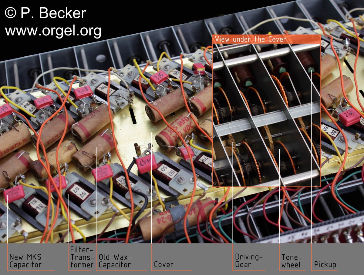
The Hammond tonewheel generator contains 48 rotating assemblies, each consisting of a shaft carrying two steel tone wheels, for a total of 91 distinct audio frequencies generated (Hammond B-3/C-3 Service Manual; bentonelectronics.com, “Servicing the Hammond Tone Generator”). The generator drive shaft runs the full length of the assembly through 24 driving gears (two each of twelve sizes) that step the synchronous run motor speed down to each tonewheel shaft. Every shaft is supported in bearings made of a special porous bronze — a sintered material that absorbs and continuously releases oil to the shaft surface (bentonelectronics.com, “Servicing the Hammond Tone Generator”).
The generator does not use grease packing or oil galleries. Instead, each porous bronze bearing is connected to a common oil trough by a cotton wicking thread. Oil placed in the trough climbs the thread by capillary surface tension and penetrates the porous bronze, lubricating the bearing surface continuously. This capillary system defines which oil may be used and exactly how it must be applied (bentonelectronics.com, “Oiling Instructions for the Hammond Organ”; Hammond B-3/C-3 Service Manual).
How the threads distribute oil along the length of the generator:
7.1.1 Why only Hammond oil
The capillary thread delivers oil by surface tension — this works only if the oil is thin enough to climb the fibre. Hammond tonewheel-generator oil is “specifically formulated to work in this environment — a low-viscosity, non-detergent mineral oil thin enough to travel the cotton thread to the bearing” (bentonelectronics.com, “Oiling Instructions for the Hammond Organ”; hammondorganco.com/oils).
Substitutes cause two classes of damage:
- Oils that are too thick (3-in-1, household oil, automotive motor oil) cannot climb the cotton thread. The oil pools in the trough; the bearings receive nothing; eventually a bearing seizes and squeals (narkive alt.music.hammond-organ, “squealing tonewheel bearing — no oiling thread”).
- Paraffin-containing or detergent oils leave deposits on the thread fibre. “The Hammond uses a very elaborate system of threads to deliver oil throughout the tone generator. Any oil that contains paraffins will cause the thread wicks to gum up and not properly distribute oil” (organforum.com; dairiki.org, “Oiling the Hammond”). A gummed thread stops wicking regardless of how much oil is added above it.
The correct oil is sold as Hammond tonewheel-generator oil (Hammond Organ Co., hammondorganco.com/oils; Tonewheel General Hospital, tonewheelgeneral.com; goffprof.com).
Warn: Never use WD-40 (or 3-in-1, sewing-machine oil, automotive motor oil, or any detergent/paraffin-containing oil) as a substitute LUBRICANT in the tonewheel generator — WD-40 has no lasting lubricating value once its carrier evaporates. (Using a penetrant ONCE to free a mechanically gummed bearing, followed immediately by Hammond oil, is a separate procedure — see the gummed-generator section.) Wrong oils either cannot climb the wicking threads (starving the bearings) or gum the threads (permanently blocking them). A gummed thread requires penetrating-solvent treatment or physical replacement — a major undertaking. Use only Hammond-branded tonewheel-generator oil in the console generator. (The Leslie motor felt pads have a more tolerant specification and accept non-detergent sewing-machine oil as a substitute; this tolerance does not extend to the generator — see Vol 11 §“Leslie motors.”)
7.2 Oiling procedure
Tools and consumables: Hammond tonewheel-generator oil (Hammond OG-1 or current equivalent — low-viscosity non-detergent mineral oil); small precision-tip dispenser or dropper if the oil bottle lacks a fine spout; LED work light; soft cloth to catch overflow.
The following procedure applies to two-switch consoles (B-3, C-3, A-100). Oiling-point locations for spinet-series organs differ; consult the Benton Electronics oiling instruction sheet for those models (bentonelectronics.com, “Oiling Instructions for the Hammond Organ”).
-
Power off the console completely. RUN switch to OFF; START switch to OFF. Unplug the mains cord. Allow the console to rest for at least 5 min (300 s) before reaching inside.
-
Locate the tone-generator oiling funnels. On the B-3/C-3, there are two funnels on the tone generator, accessible after opening the rear panel or tilting the manuals to gain access. The funnels may be brass (older consoles) or white plastic (later production) (bentonelectronics.com, “Oiling Instructions”).
-
First fill — left funnel: apply Hammond oil to the left funnel until it is full (a funnel-full). Allow the oil to drain completely into the trough below before proceeding. Watching the funnel drain confirms the thread and trough passage are open and wicking normally.
-
First fill — right funnel: repeat Step 3 for the right funnel — fill to full, observe drain.
-
Second fill — left funnel: once the left funnel has drained, fill it a second time to full. This double-fill is the specified quantity for a healthy, unblocked system (bentonelectronics.com, “Oiling Instructions”). A numeric volumetric quantity in mL is not specified in the period documentation; the governing measure is “fill the funnel twice, letting it drain between fills” — not a counted drop volume.
-
Second fill — right funnel: repeat Step 5 for the right funnel.
-
Motor / scanner felt tub (left-rear of console): locate the felt tub that lubricates the run motor bearings and the scanner shaft. Moisten the felt only — do not flood or fill it. Flooding the tub causes oil to migrate by capillary action onto the vibrato scanner’s capacitor plates, degrading or destroying the vibrato (bentonelectronics.com, “Oiling Instructions”). For the remedy if over-oiling has already reached the scanner, see Vol 10 §“Scanner plate cleaning.”
-
Optional upper oil cups (where fitted): some B-3/C-3 chassis carry an additional pair of cups above the motor/scanner area. If present: left cup (motor/scanner) — fill to half-full; right cup (generator) — fill to the top (bentonelectronics.com, “Oiling Instructions”).
-
Scanner shaft bearing drop: when the motor/scanner felt tub is serviced, place one very small drop (est. ≈ 0.05 mL to 0.10 mL / approx. 0.002–0.003 fl oz) of Hammond oil directly on the scanner shaft bearing. One drop only — excess migrates onto the scanner plates (bentonelectronics.com). The exact drop volume is not numerically specified in the period literature; one drop from a standard dispenser tip is (est.).
-
Replace all covers and panels. Do not run the console and judge the result immediately — oil requires a week or more to travel the cotton threads to every bearing after filling (bentonelectronics.com, “Oiling Instructions”). Same-day performance is not a valid indicator of oiling quality.
Warn: Over-oiling the motor/scanner felt tub is as damaging as under-oiling. Excess oil migrates by capillary action onto the vibrato scanner’s capacitor plates and insulating spacers, shorting the signal path and producing a weak or erratic vibrato. Moisten the felt tub only — a visibly wet or dripping felt is already too much (bentonelectronics.com).
Warn: Do not add extra oil to “speed up” wicking to a noisy bearing. Capillary physics governs the rate; flooding the trough does not accelerate delivery but does create surplus oil that migrates to the scanner plates and key contacts. Add the specified double-fill once per year and allow a week for the system to equilibrate.
Oiling schedule — two-switch console (B-3, C-3):
Table 1 — Oiling schedule — two-switch console (B-3, C-3):
| Point | Quantity | Interval | Source |
|---|---|---|---|
| Tone-generator funnels (×2) | Fill twice each (fill, drain, repeat) | Annually | bentonelectronics.com |
| Motor / scanner felt tub | Moisten the felt only | Annually | bentonelectronics.com |
| Upper oil cups — left (motor/scanner), if fitted | Half-full | Annually | bentonelectronics.com |
| Upper oil cups — right (generator), if fitted | To the top | Annually | bentonelectronics.com |
| Scanner shaft bearing | One very small drop (est. ≈ 0.05–0.10 mL / approx. 0.002–0.003 fl oz) | When tub is serviced | bentonelectronics.com |
| Oil type (all generator and motor points) | Hammond tonewheel-generator oil (low-viscosity, non-detergent mineral oil) | — | hammondorganco.com/oils |
Note: An organ with unknown service history, or more than one year since last oiling, should receive this procedure as a catch-up dose and then be returned to the annual schedule (bentonelectronics.com; dairiki.org, “Oiling the Hammond”). New oil may take longer than a week to reach dried-out bearings in a badly neglected instrument; a single application may not fully restore lubrication — assess after two weeks and add a second dose if squealing persists.
7.3 Diagnosing & freeing a gummed generator
7.3.1 Symptoms
A generator whose oiling threads have gummed — from wrong oil, from years of disuse, or from aged oil that has varnished on the thread fibre — presents with a recognisable cluster of symptoms:
Table 2 — of symptoms
| Symptom | Cause | Notes |
|---|---|---|
| Slow or failed start — START motor runs but generator shaft does not reach speed | Bearings sticky from dried or varnished oil; pinion sticky | Most common in long-stored instruments |
| Sluggish run-up — generator reaches speed slowly or speed wavers before locking | Partial bearing friction; run motor fighting sticky bearings | Also verify run-motor winding resistance (§“Run motor,” below) |
| Squealing or rumbling from the generator | One or more bearings running dry — wick to that bearing gummed or broken | Squeal frequency corresponds to the affected tonewheel |
| Weak or absent individual notes | Bearing so dry the shaft binds; tonewheel position disturbed relative to pickup | Rule out key-contact and drawbar causes first (Vol 09) |
| Generator shaft stiff or immovable by hand | Severe varnish on bearing surfaces | Immediate service required before powering on |
Diagnostic test — hand rotation: with the console powered off and unplugged (Vol 06 §“Safety first”), try to rotate the tone-generator shaft by hand at the generator end near the run-motor coupling. If the shaft is stiff, resists rotation, or cannot be turned at all, gumming is confirmed and must be resolved before the console is run again (dairiki.org, “Tone Generator Won’t Start”).
7.3.2 Cause
Old oil — particularly wrong-type oil applied at some point in the instrument’s history — varnishes onto the cotton thread fibre and the porous bronze surface. The thread loses capillary mobility; the varnish acts as a plug. Even correct Hammond oil, if left without top-up for many years, can thicken and reduce wicking — though this is far less severe than the damage caused by detergent or paraffin-containing substitutes (organforum.com, “Oiling thread”; bentonelectronics.com, “Oiling Instructions”).
7.3.3 The fix — re-oiling and freeing
Warn: Do not attempt to free a gummed generator with aggressive solvents (acetone, methyl ethyl ketone, lacquer thinner). These attack the cotton thread fibre itself, weakening and destroying the very system that must be preserved. If the thread is destroyed, the bearing it serves cannot receive oil without a generator teardown to re-string. Start with the gentlest effective penetrant.
For mild gumming (shaft stiff but movable by hand):
Tools: Hammond tonewheel-generator oil; small dropper or syringe; work light; gloves.
- Confirm power off and mains cord unplugged (Vol 06 §“Safety first”).
- Apply Hammond oil directly to generator bearing access points — drip oil around the shaft ends and any accessible bearing locations in addition to filling the funnels per the standard oiling procedure above.
- Work the shaft by hand — rotate the generator shaft back and forth, gradually increasing freedom of movement. If the start-motor pinion shaft is accessible, slide it in and out on its shaft while rotating (bentonelectronics.com, “Hammond Generator Start Motor”). This distributes oil mechanically to the bearing surface.
- Allow to soak — place a full charge of Hammond oil in the funnels and allow it to penetrate for at least 24 h (86 400 s) before attempting to start the organ. Check the funnels and re-fill if they have emptied.
- Attempt a careful start — using the variac ramp procedure (Vol 06 §“Powering up a long-stored instrument”), bring the console up slowly. Listen for reduced squealing and smooth run-up. Several oiling cycles over successive days may be needed for a badly neglected instrument.
For severe gumming (shaft immovable or extremely stiff):
Additional materials: light penetrating fluid — WD-40 or a 50/50 mixture (by volume) of Hammond organ oil and lighter fluid (trade practice; dairiki.org, “Tone Generator Won’t Start”); shop rags; oil catch tray.
-
Steps 1–3 of the mild-gumming procedure first. Hand-working with Hammond oil alone is always attempted before introducing a penetrating fluid.
-
Apply penetrating fluid sparingly to the generator shaft ends and exposed bearing access points. WD-40 loosens varnish and allows shaft movement; a 50/50 Hammond oil / lighter-fluid mixture is reported to soften gum on oiling threads within minutes in severe cases (dairiki.org, “Tone Generator Won’t Start”). Apply to the problem area; do not flood the generator interior.
-
Work the shaft while the penetrant is active. The goal is to break the varnish grip on the shaft and bearing surface.
Warn: WD-40 and lighter fluid both evaporate quickly. If the shaft frees up after penetrant application, the bearings are left with no lubricant once the penetrant evaporates. Follow every penetrant application immediately with Hammond tonewheel-generator oil in the funnels and at every accessible bearing point. Failing to follow up guarantees bearing starvation and return squeal (dairiki.org, “Tone Generator Won’t Start”).
-
Protect the oiling threads. When working around the generator shaft and pinion, avoid dislodging or snapping the cotton wicking threads. “Watch carefully for the oiling string that goes from the oiling tub to the shaft and bearing — do not break this string while working” (dairiki.org, “Tone Generator Won’t Start”). A broken thread cannot be repaired without generator access; the affected bearing must be spot-oiled by dropper until the thread can be replaced.
-
After freeing: full annual oiling — once the shaft rotates freely, perform the complete oiling procedure (§“Oiling procedure” above). Allow at least one week (7 days) before drawing conclusions about the instrument’s lubricated state.
Warn: Do not use solvent flushing as a shortcut for thorough oiling. Solvents that strip all oil from the threads leave the cotton fibre dry and brittle. The threads function by retaining an oil film within the cotton; repeated solvent washing shortens their service life and can destroy the capillary channel permanently. Use penetrant only to free mechanical gumming; switch to Hammond oil as the working lubricant as soon as the shaft is movable.
7.4 Start & run motors
The generator assembly incorporates two distinct motors: a start motor (shaded-pole induction type) that brings the generator up to speed from rest, and a run motor (synchronous type) that locks to the mains frequency and maintains pitch-stable drive once the generator is running. Both share lubrication from the capillary oiling system and are serviced in place without removing the generator (bentonelectronics.com, “Hammond Generator Start Motor”; bentonelectronics.com, “Hammond Synchronous Run Motor”).
7.4.1 The start motor and spring-return pinion
The start motor is a shaded-pole induction motor — it builds torque regardless of mains frequency phase and does not require synchronous lock. It drives the generator via a sliding pinion gear on its output shaft (Hammond B-3/C-3 Service Manual; bentonelectronics.com, “Hammond Generator Start Motor”):
- The pinion normally rests in the “out” position (slid toward the run-motor end), held by a light-duty return spring. In this position a pin on the shaft prevents the generator from freewheeling — the pinion is in the drive train but the start motor is not turning.
- When the START switch is pressed, current energises the start motor; a larger clutch spring drives the pinion “in” (toward the start motor) to mesh with the generator drive gear. A mechanical click or clunk as the pinion seats is normal.
- Once the run motor locks to mains frequency and the RUN switch is engaged, the start motor de-energises. The light return spring pulls the pinion back to the out position, disengaging the start motor from the drive train.
Warn: Do not leave the console running on the START switch alone for extended periods. The shaded-pole start motor is rated only to bring the generator to speed, not for continuous-duty operation. Extended START-only running overheats the shaded-pole windings and damages the sliding pinion assembly (organforum.com; bentonelectronics.com, “Hammond Generator Start Motor”). Engage the RUN switch within a few seconds of the generator reaching speed, then release START.
Start motor and spring-return pinion — two-position diagram:
Start motor service procedure:
Tools: Hammond oil; small dropper; DMM (Ω range); work light; slim screwdriver to slide pinion if needed.
- Confirm power off and mains cord unplugged.
- Check the return spring. Push the pinion shaft inward by hand and release. The shaft should spring back freely to the out position within approximately 1 s. If it does not return, the return spring is weak or the shaft is sticky from dried oil (bentonelectronics.com, “Hammond Generator Start Motor”).
- Oil the pinion shaft. Apply a small drop of Hammond oil to the pinion shaft where it slides in its housing. Slide the pinion in and out several times to work the oil into the contact surface.
- Verify oiling thread for start motor bearings. The start motor bearings receive oil from the same capillary system as the generator bearings — via threads from the oiling trough. Confirm threads are intact and the trough holds oil (Step 2 of the annual oiling procedure).
- Test field coil continuity if motor is suspected failed. Set the DMM to the Ω range. Measure across the start motor field coil terminals. An open circuit (OL) or a dead short (0 Ω) indicates coil failure; the motor must be replaced. A specific coil resistance target for the start motor is not published in the consulted sources; the value is (est. — verify against the unit’s own service manual).
7.4.2 The run motor
The run motor is a non-self-starting synchronous motor — it cannot start from rest under load, but once the start motor has brought the generator shaft to near-synchronous speed, the run motor locks to the mains frequency and maintains pitch-stable drive indefinitely (bentonelectronics.com, “Hammond Synchronous Run Motor”; Hammond B-3/C-3 Service Manual).
60 Hz and 50 Hz regional variants use different motors (different pole counts) optimised for each mains frequency; the specifications below reflect the 60 Hz B-3/C-3 unless noted.
Run motor specifications:
Table 3 — Run motor specifications:
| Parameter | Value | Source |
|---|---|---|
| Motor type | Non-self-starting synchronous | Hammond B-3/C-3 Service Manual |
| Operating speed (60 Hz mains) | 1 200 rpm | bentonelectronics.com |
| Operating speed (50 Hz mains) | 1 500 rpm | bentonelectronics.com |
| Field coils | 2, wired in parallel | Hammond B-3/C-3 Service Manual |
| Each coil resistance (individual) | ≈ 180 Ω | bentonelectronics.com; dairiki.org |
| Both coils in parallel (healthy) | ≈ 90 Ω | bentonelectronics.com; dairiki.org |
| One coil open (one failed) | ≈ 180 Ω (only one coil reading) | bentonelectronics.com |
| Both coils open (motor failed) | OL (infinite) | bentonelectronics.com |
Note: The 60 Hz and 50 Hz synchronous speeds (1 200 rpm and 1 500 rpm respectively) differ by design — the tonewheel tooth counts are calibrated for one specific speed. A 60 Hz console run on 50 Hz mains runs slower (1 000 rpm instead of 1 200 rpm) and therefore produces flat pitch across all notes — approximately 3 semitones flat (1 000/1 200 ≈ 0.833, about −316 cents); a 50 Hz console (1 500 rpm) run on 60 Hz mains runs at 1 800 rpm and produces sharp pitch (dairiki.org). Export consoles are built for 50 Hz (Vol 02 §2.1).
Start and run motor wiring (simplified schematic):
Run motor service procedure:
Tools: Hammond oil; dropper; DMM (Ω range); work light.
- Confirm power off, mains cord unplugged, and HV filter capacitors discharged and verified at 0 VDC (Vol 06 §“Safety first” and §“Capacitor-discharge procedure”).
- Check the felt tub oil level. The run motor bearings receive oil from the motor/scanner felt tub. The felt should be moist — not dry, not dripping (§“Oiling procedure,” Step 7).
- If the run motor is sluggish or slow to lock: apply Hammond oil directly to the run motor bearing shafts — front (accessible from the generator end) and rear. “Apply oil directly to bearings; manually rotate the shaft until it spins freely with gradual deceleration” (bentonelectronics.com, “Hammond Synchronous Run Motor”). Accessing the rear bearing requires removing the vibrato scanner (Vol 10 §“Scanner removal”).
- Test field coil resistance. Set the DMM to Ω. Measure across the run motor terminal pair. Interpret per the table above: ≈ 90 Ω = both coils healthy; ≈ 180 Ω = one coil open (motor unreliable, replacement needed); OL = both open (replace motor).
- Separate motor from generator if isolated testing is needed. The run motor is mechanically coupled to the generator via two coupling springs (bentonelectronics.com, “Hammond Synchronous Run Motor”). Removing these springs allows independent rotation of the run motor and generator shafts. Re-fit both springs before returning to service; running without the springs allows each assembly to overspeed independently.
Warn: The run motor is non-self-starting — if the start motor fails to bring the generator to synchronous speed and the RUN switch is then engaged, the run motor winding is energised against a near-static load. This draws locked-rotor current and rapidly overheats the winding. If the organ fails to come up to speed within approximately 30 s to 60 s (est.) of the START switch being engaged, power off immediately and diagnose the start motor before attempting again.
7.5 Tonewheels & pickups
7.5.1 Tonewheel construction
Each of the 48 tonewheel shaft assemblies in the B-3 generator carries two steel tone wheels — 91 distinct audio frequencies in total (the generator is often described as a “91-frequency generator”; some frequencies share a pickup) (Hammond B-3/C-3 Service Manual; bentonelectronics.com, “Servicing the Hammond Tone Generator”). Each tonewheel is:
- A steel disc approximately 2 in (51 mm) in diameter, precisely machined with a set number of raised teeth around its perimeter (bentonelectronics.com, “Servicing the Hammond Tone Generator”).
- Tooth count ranges from 2 teeth (lowest generator frequencies, low bass region) to 192 teeth (highest generator frequencies, upper treble region), scaled so that the correct audio frequency is produced at the generator’s synchronous speed (Hammond B-3/C-3 Service Manual; Vol 02 §2.2).
The relationship is: f (Hz) = tooth count × shaft rpm ÷ 60, where “shaft rpm” is the speed of the specific gear shaft carrying that wheel — not necessarily the synchronous motor’s base speed. The generator’s internal gear train runs the highest-frequency wheels above the 1 200 rpm base shaft; the actual top tonewheel frequency is approximately 5 920 Hz (F#7), not the 3 840 Hz that the naive “192 × 1 200 ÷ 60” formula produces when the gear ratio is omitted (dairiki.org/HammondWiki, GearRatio; Vol 02 §“Frequency derivation”).
7.5.2 Pickup construction
Associated with each tonewheel is a rod-magnet pickup:
- A magnetised steel rod approximately 1/2 in (12.7 mm) in diameter and 4 in (102 mm) in length (bentonelectronics.com, “Servicing the Hammond Tone Generator”; Hammond B-3/C-3 Service Manual).
- A coil of wire wound near one end of the rod. The tip of the magnet at the coil end is ground to a sharp edge and positioned close to the edge of the rotating tonewheel.
- As tonewheel teeth pass the magnetised tip, the changing magnetic flux induces an AC voltage in the coil at the tooth-pass frequency — the generated tone.
One pickup coil corresponds to each tonewheel; the 91 pickup coils are wired into the key-contact matrix (Vol 02 §2.3; Vol 09). Each coil connects to ground on one end and to the signal/filter network on the other (bentonelectronics.com, “Generator Pick-Ups”).
Note: Pickup coil resistance varies between frequency positions — higher-frequency coils differ from lower-frequency coils. No single target resistance applies across all 91 pickups (bentonelectronics.com, “Generator Pick-Ups”). When checking individual coils by resistance, compare against the service manual value for that specific frequency position rather than a universal target.
7.5.3 Dead-note triage
A completely dead note — absent regardless of which drawbar is pulled — must be traced through a triage sequence before attributing it to a tonewheel or pickup fault. Key contacts (Vol 09) are the most common cause and must be ruled out first.
Table 4 — Dead-note triage
| Step | Test | Interpretation |
|---|---|---|
| 1 | Play the dead note with all drawbars pulled to 8. Is the note absent on every drawbar, or only some? | Some drawbars only → key contact fault for that harmonic (Vol 09 §“Key contacts”). All drawbars dead → generator or wiring fault; continue triage. |
| 2 | Measure pickup coil resistance (DMM, Ω range) at the pickup terminal | Open circuit (OL) → broken wire, broken coil. Dead short (0 Ω) → shorted coil or wiring short. Finite reading → coil electrically intact; continue. |
| 3 | Inspect the tonewheel for visible damage (cracked disc, missing tooth, debris lodged against the wheel edge) | Visible damage → generator specialist assessment. No damage → continue. |
| 4 | Check the generator filter capacitor associated with that frequency (bentonelectronics.com, “Generator Pick-Ups”; Vol 08 §“Generator filters”) | A failed filter cap on that frequency can silence the note while the pickup is intact. |
| 5 | Inspect wiring from pickup terminal strip to key-contact bus for broken traces or broken solder joints | A broken connection at the pickup end silences the note while the coil reads normally. |
Warn: Do not attempt to adjust the air gap between the pickup magnet tip and the tonewheel without the Hammond factory alignment jig and the calibration procedure from the service manual. The service manual states it is “not recommended that the serviceman attempt this adjustment” without proper equipment (bentonelectronics.com, “Generator Pick-Ups”). Inward adjustment risks contact between the magnet tip and the spinning tonewheel — catastrophic damage to both. Outward adjustment reduces output level and alters tone timbre. Do not handle the rod-magnet pickups roughly; dropping or striking a magnet can demagnetise it, eliminating its output permanently.
If a pickup coil has definitively failed: there is no in-field repair. “If you have a bad pick-up, there is in reality no repair here. These pick-ups are sandwiched into the generator as it is put together. Also, there are no parts you can order” (bentonelectronics.com, “Generator Pick-Ups”). Practical resolutions:
- Trek II dead-note replacement module — an electronic circuit that synthesises the missing frequency and injects it into the signal path, eliminating the dead note without generator disassembly (bentonelectronics.com, “Generator Pick-Ups”; Vol 05 §“Trek II”).
- Generator rebuild by a specialist — pickup replacement requires full generator disassembly and is a last resort for an otherwise-clean, high-value console.
Note: Pickup coils “practically never fail” (bentonelectronics.com, “Generator Pick-Ups”). Before accepting a pickup failure, exhaust the full triage above — including key contacts (Vol 09), generator filter caps (Vol 08), and wiring checks. Most dead notes resolve at Step 1 (key contacts) or Step 4 (filter caps).
7.6 Removing the generator
Generator removal is rarely necessary for routine service — oiling, start/run motor checks, and pickup triage are all performed in place. Removal is indicated when:
- The generator requires specialist rebuild (failed pickup, broken tonewheel shaft, severe bearing damage beyond in-place treatment).
- The console must be moved through a doorway narrower than the assembled cabinet and the generator’s weight makes frame tilting unsafe (Vol 06 §“Moving & lifting a console”).
- A full internal overhaul requires complete access to the console chassis.
Warn: The tonewheel generator is estimated at approximately 45 lb (20 kg) (est.; dairiki.org/HammondWiki, “WhatDoesAHammondWeigh”; organforum.com service discussions; Vol 06 §“Weights”). Two persons are required for removal and re-installation. Do not lift by the wiring harness, pickup terminal strip, or oiling trough — none of these are structural members. Lift from the generator frame only (Hammond B-3/C-3 Service Manual).
Warn: Before beginning removal, the console must be fully unplugged, all wiring harnesses tagged and disconnected, and the AO-28 / power-supply capacitors discharged and verified at 0 VDC (Vol 06 §“Capacitor-discharge procedure”). The generator wiring includes signal lines at audio potential (safe) and the oiling trough holds residual oil that will spill if the assembly is tipped without preparation.
High-level removal procedure (refer to the Hammond B-3/C-3 Service Manual for exact fastener locations and torque specifications):
Equipment: two persons; tape and marker for labelling harness connectors; pen and notepad; clean rags; oil catch tray placed below; wood blocks or foam padding for a resting surface.
- Power off, unplug, and discharge the console. Verify 0 VDC at all HV points per Vol 06 §“Capacitor-discharge procedure.”
- Tag and disconnect all wiring harnesses running from the generator to the key-contact matrix, the AO-28, and the run/start motor terminal block. Label every connector and its mating socket before disconnecting — the harness layout is dense and reassembly without labelling is error-prone.
- Drain the oiling trough. Remove as much residual oil as possible from the funnels and trough using a dropper or bulb syringe before tilting the assembly. Place the oil catch tray below.
- Unhook the four suspension springs on which the generator assembly rides. These springs isolate the generator from chassis vibration; they attach at four points on the generator frame (Hammond B-3/C-3 Service Manual). Support the generator’s weight by hand as each spring is released — do not allow the assembly to drop.
- Lift and remove from the rear of the console. Person one supports the generator body; person two guides the assembly rearward and clear of the console frame. Lower the generator onto the prepared padded surface, keeping it level to prevent oil spill from residual trough contents.
To reinstall: reverse the procedure. Reconnect every harness connector to its labelled socket; re-hook all four suspension springs; perform the full annual oiling procedure (§“Oiling procedure”) before returning the console to service.
Note: When transporting a fully assembled console over a long distance, the generator should be secured against swinging on its suspension springs to prevent the heavy assembly from shifting and damaging the frame, wiring, or console structure (organforum.com service discussions).
Sources: Hammond B-3/C-3 Service Manual (period document; generator structure, 48 rotating assemblies, tonewheel construction, suspension springs, start/run motor description, pickup construction); bentonelectronics.com — “Oiling Instructions for the Hammond Organ” (funnel fill procedure for two-switch consoles, motor/scanner felt tub, annual interval, over-oiling migration warning, oil takes a week or more to reach bearings); “Servicing the Hammond Tone Generator” (48 assemblies, porous bronze bearings, cotton thread system, oil trough, 2 in / 51 mm tonewheel diameter, rod-magnet pickup dimensions 1/2 in × 4 in / 12.7 mm × 102 mm); “Hammond Generator Start Motor” (shaded-pole type, clutch and return springs, pinion slides in/out, manual spring-back test, oiling thread check); “Hammond Synchronous Run Motor” (synchronous non-self-starting, 1 200 rpm at 60 Hz, 1 500 rpm at 50 Hz, coil resistance ≈ 180 Ω each / ≈ 90 Ω parallel, felt tub lubrication, coupling springs for isolation); “Generator Pick-Ups” (rod-magnet construction, resistance variability, dead-note triage, no-repair guidance, Trek II alternative); dairiki.org / HammondWiki — “Tone Generator Won’t Start” (hand-rotation diagnostic, gummed generator symptoms, penetrant procedure — WD-40 then Hammond oil; 50/50 Hammond oil / lighter fluid for severe gumming; oiling thread fragility warning, days-to-weeks for new oil after freeing); organforum.com — “Oiling thread,” “Hammond Organ Tonewheel Oil” (paraffin-oil gumming mechanism, thread function); narkive alt.music.hammond-organ — “squealing tonewheel bearing — no oiling thread” (bearing starvation symptom from gummed/wrong-oil wick); goffprof.com and tonewheelgeneral.com (general B-3 service reference; oil product specifications); hammondorganco.com/oils (Hammond OG-1 and current oil products). Numeric values: run-motor coil resistance (≈ 180 Ω / ≈ 90 Ω) is VERIFIED per bentonelectronics.com and dairiki.org. Run-motor speeds (1 200 rpm / 1 500 rpm) are VERIFIED per bentonelectronics.com. Oiling quantity for funnels is specified procedurally (“fill twice, let drain between”) per bentonelectronics.com — no mL figure is stated in the period documentation and none has been invented here. Scanner bearing drop volume (est. ≈ 0.05–0.10 mL) and start-motor coil resistance are (est.) — not numerically specified in consulted sources. Generator weight approximately 45 lb / 20 kg is (est.) per dairiki.org/HammondWiki (“WhatDoesAHammondWeigh”) and organforum.com trade consensus. No electrical or dimensional value has been invented; all (est.) items are explicitly flagged. Cross-references: Vol 02 §2.1–2.2 (synchronous motor theory, tonewheel frequency table), Vol 05 §“Trek II” (dead-note replacement module), Vol 06 §“Safety first,” §“Capacitor-discharge procedure,” and §“Moving & lifting a console” (all safety and lifting prerequisites), Vol 08 §“Generator filters” (filter capacitor check in dead-note triage), Vol 09 §“Key contacts” (dead-note triage step 1 — most common cause), Vol 10 §“Scanner plate cleaning” and §“Scanner removal” (run motor rear bearing access; over-oiling remedy), Vol 11 §“Leslie motors” (Leslie motor-oil substitute tolerance), Vol 18 (reference frequency table and tooth-count list).
Comments (0)